This article reviews the basic theory of waves and wave motion focusing on a practical application: electronics and communications. In addition, images and graphs of moving waves are provided to facilitate the understanding of the concepts explained.
The text is organized as follows. First, waves are defined from a general and also mathematical point of view. Then, for the case of a single travelling wave, the typical fundamental parameters are derived. Subsequently, the case of two waves overlapping in opposite directions is analyzed. Finally, the analysis is generalized to the case of propagation of signals composed of multiple waves.
The table of contents is as follows:
1. What are the Waves?
In this section, waves are defined in practical terms and in mathematical terms.
1.1 Definition of Wave
In general terms, a wave is simply a disturbance that propagates dynamically in a medium.
In the particular case of electronics and communications, these disturbances are called signals because they carry information. These disturbances occur on an electrical parameter such as voltage, current, power or electromagnetic fields.
1.2 Wave Equation
In mathematical terms, a wave is any disturbance that satisfies the wave equation. Simplistically, for a periodic wave of amplitude u, velocity v, and propagating in time t along the x-axis, the wave equation is as follows:
\begin{equation} \frac{1}{v^2}\frac{\partial^2u}{\partial t^2}=\frac{\partial^2u}{\partial x^2}\end{equation}
Although equation (1) is satisfied with periodic perturbations u(x,t) of any aspect, in electronics and communications the solutions to the equation that make physical sense are typically sinusoidal. Therefore, such waveforms are the ones used in the rest of the text.
2. Travelling Waves
This section studies in detail the sinusoidal wave, which represents the simplest unit that we can find in communications. From different graphs, static and moving, the main parameters of the wave are derived. These terms are basic to understand and build more advanced concepts related to communications.
2.1 Mathematical Wave Function
Since a travelling wave propagates along an x-axis during time t, the wave function must be dependent on both parameters. Consequently the wave can be represented as a function f(x,t). Furthermore, as mentioned above, the wave has a sinusoidal aspect, so the function can be written as follows:
\begin{equation} f(x,t) = \cos(kx - \omega t)\end{equation}
Where the physical meaning of k and ω is explained in the following sections. For simplicity a wave amplitude A equal to unity is assumed.
Therefore, since the wave function depends on two variables (position x and time t), different types of graphical representations can be made. As explained below, depending on which variable is left fixed, different wave characteristics can be illustrated and derived.
2.2 Waves at a Space Point
Fixing the value of x, the function f(x,t) represents the evolution of the wave over time at a point of space. For example, it can be obtained the wave propagating through the medium and detected at a receiver located at position \footnotesize x_o . For mathematical simplicity, but without losing generality, this case is analyzed for the origin of coordinates:
\begin{equation} f(x,t)\Bigr|_{x=x_o=0} =f(0,t) = \cos(\omega t)\end{equation}
Where ω represents the angular frequency in rad/s
2.2.1 Frequency
From the previous equation it is derived that the frequency indicates the repetition rate of the sinusoidal wave over time. It can be expressed in angular form, ω (rad/s), or in cycles per second, f (Hz). Because of the periodicity of 2π radians in sinusoidal functions, both notations of frequency are related by the following identity:
\begin{equation} \omega = 2\pi f \end{equation}
2.2.2 Period
Directly related to the frequency, or repetition rate over time, the period T indicates the time that a complete cycle of the wave lasts. Or, in other words, the time that elapses until the passage through the same point of the cycle occurs again at position \footnotesize x_o . Obviously, the higher the frequency, the shorter the period. This effect is reflected in the following graph:
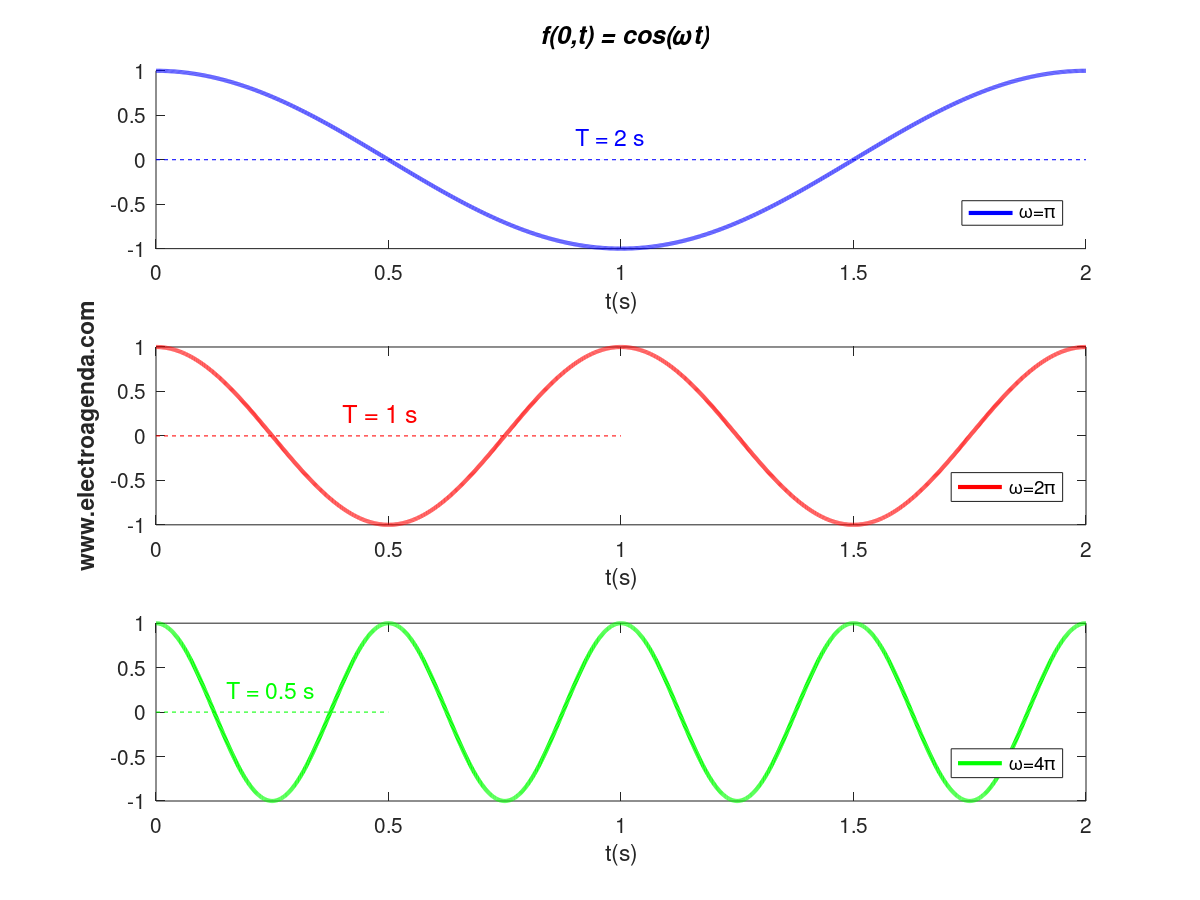
From both equation (3) and the above graph it can be deduced that:
\begin{equation} T = \frac{2\pi}{\omega}=\frac{1}{f}\end{equation}
2.3 Waves in a Time Instant
Returning to the function of two variables f(x,t), if we fix the value of time t, we obtain a representation or picture of the wave along the x-axis for an instant in time. Again without loss of generality, this case can be analyzed for the origin of time:
\begin{equation} f(x,t)\Bigr|_{t=t_o=0} =f(x,0) = \cos(kx)\end{equation}
Where k is the equivalent of the angular frequency in the space domain, with units of rad/m.
2.3.1 Wavelength
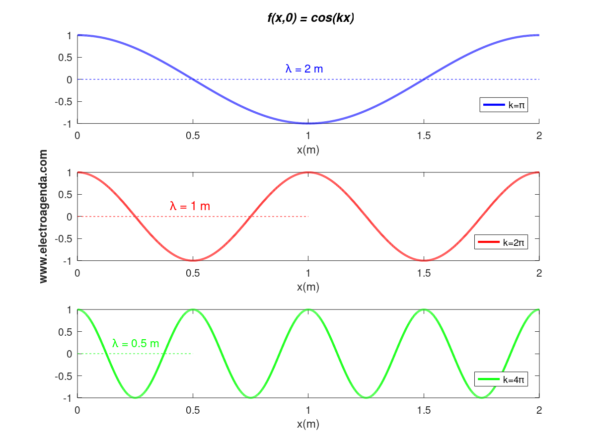
Just as, according to equation (3), the wave is periodic with period T in the time domain, according to equation (6) the wave is equally periodic in the space domain. In this case the spatial period is called the wavelength, λ, and, equivalently, is given by the expression:
\begin{equation} \lambda = \frac{2\pi}{k}\end{equation}
Consequently, the higher the value of k, the lower the λ, and vice versa. This effect is reflected in the following graph:
2.3.2 Wavenumber
The constant k is typically referred to as the wavenumber. And it is usually defined as the number of wavelengths that exist in 2π meters. Indeed, a value of k equal to 1 implies a wavelength of 2π meters. In the vast majority of cases, k is also equal to the so-called propagation constant β.
2.4 Waves in Motion
So far, static representations of a simple sinusoidal wave have been shown. These figures have made it possible to derive basic parameters that characterize the wave: angular frequency, period, wave number and wavelength.
However, since the wave is moving, such an important parameter as the propagation velocity has yet to be shown. In this section this velocity is derived and illustrated with moving graphs.
2.4.1 Phase velocity
The phase velocity represents the propagation velocity of any one phase of the wave. For example, if a simple moving wave is observed, the speed at which the peak, or zero, or a point of any amplitude propagates, is the phase velocity.
There are many ways to demonstrate phase velocity. The simplest definition is derived from the two graphs above, those showing the wavelength λ and the period T. Indeed, since a wavelength takes one full period to travel, it follows that:
\begin{equation} v_p = \frac{\lambda}{T} = \frac{\omega}{k}\end{equation}
Where equations (5) and (7) have been used to obtain the relationship with the frequency. Note that with the units used in the text, the result is obtained in m/s.
For a more global view of the phase velocity, it is recommended to consult the following reference [1] and the following link.
2.4.2 Graphical Representation
Section 2.3 explained how to represent a wave in space at a given instant of time. Consequently, the wave in motion is observed by plotting the wave function in space at consecutive instants.
Three moving waves with a wavelength of 1 m are illustrated below, each with a different phase velocity (and expressed in m/s):
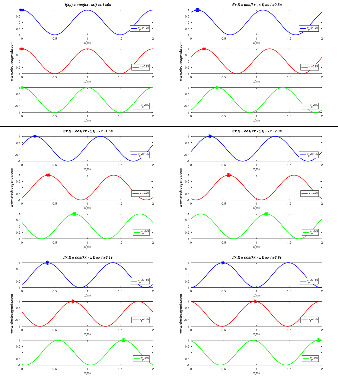
In the time span shown of duration 4 seconds it is verified that the wave, or the phase point marked with the indicator, travels the expected distances: 0.5 m when the phase velocity is 0.125 m/s, 1 m when the phase velocity is 0.25 m/s, and 2 m when the phase velocity is 0.5 m/s.
2.4.3 Wave Propagation Direction
All the conclusions made so far are independent of the direction of wave propagation. From equation (2), and assuming that the frequencies are entered with positive values, it can be deduced that the sign of k indicates the direction of wave propagation. Indeed, a value of k > 0 implies that the wave propagates to the right and k < 0 translates into a wave propagating to the left.
The following is the same simulation as in the previous section, changing the sign of k and, consequently, the direction of propagation:
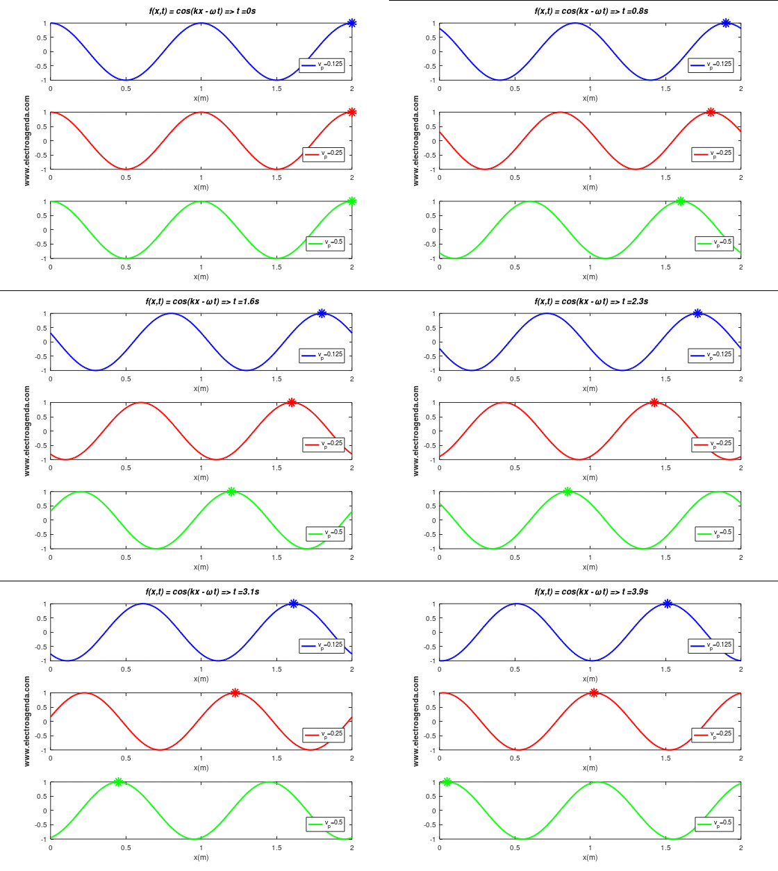
Any of the moving images shown serve as an example of waves propagating in a transmission medium, such as a cable or the air.
3. Standing Waves
Standing waves occur when two travelling waves propagating in opposite directions overlap. While in a simple wave all points in x-space have the same maximum amplitude, in a standing wave the maximum amplitude is not constant, but dependent on the x-position.
In this section, standing waves are introduced mathematically. In addition, standing waves in motion are illustrated, allowing to visualize the resulting effect.
3.1 Mathematical Demonstration
First, two travelling waves propagating in opposite directions are defined. For simplicity, the amplitude of both waves is considered to be the same. Assuming k>0, the waves traveling to the right and left are, respectively, as follows:
\begin{equation} f^{+}(x,t) = \cos(kx - \omega t)\end{equation}
\begin{equation} f^{-}(x,t) = \cos(-kx - \omega t)\end{equation}
Applying the following trigonometric identity:
\begin{equation} \cos(a) +\cos(b)=2 \cos\left(\frac{a+b}{2}\right)\cos\left(\frac{a-b}{2}\right)\end{equation}
The following result is obtained:
\begin{equation} f^{+}+f^{-} = \underbrace{2\cos(kx)}_{\text{Amplitude}}\cos(\omega t)\end{equation}
Therefore, for standing waves, it is shown that each position in x-space has an associated maximum amplitude that follows a simple harmonic motion.
3.2 Graphical Representation
Next, it is shown the movement of waves propagating in opposite directions and the resulting standing wave:
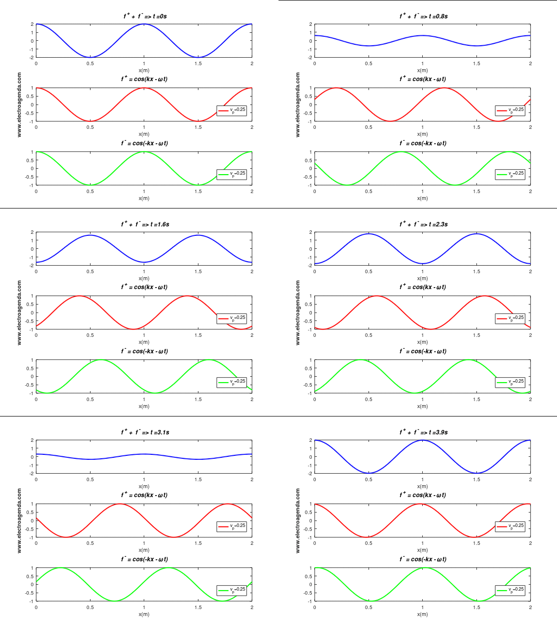
It can be seen that the qualification of the standing wave comes from the visual effect it produces. Indeed, it looks as if the resulting wave does not move and that each particle remains at the same position x. Note that the period of the standing wave, its repetition rate, is equal to the period of the two overlapping waves, namely 4 seconds.
3.3 Applications: RF and Microwaves
In electronics and communications, standing waves appear mainly in the field of radio frequency and microwaves. The analysis for these cases is more complex than the one shown here, since waves with different amplitudes and phase shifts can be superimposed. For a more in-depth treatment of this case the following references are recommended [2] [3].
4. Signals
Electronics and communications study the transmission of information by means of signals. Therefore, this section describes the formation of signals from waves of different frequencies. Finally, the propagation of a signal is represented and the concept of a group is introduced.
4.1 Signal Generation
In practice, signals are composed of a set of waves, each with its corresponding parameters (frequency ω, amplitude A, wavenumber k…) [4]. Therefore, simplifying, a signal can be represented as a summation of waves:
\begin{equation} s(x,t) = \sum_{i}f_{i}(x,t) = \sum_{i}A_i\cos(k_ix-\omega_i t) \end{equation}
Where it must be taken into account that the variables k and ω can be related by any function, determined by the transmission medium. Note that the term transmission medium is used here in a broad sense, so that it also refers to the passage through any electronic component.
4.2 Signal Propagation
The simplest case, which is not the most common, occurs when the phase velocity of all waves is the same. According to equation (8), this implies that the ratio ω/k is constant in all the waves that compose the signal. In that case the signal remains unchanged as it propagates through the medium. Therefore, no signal distortion occurs.
In practice, signal propagation is a more complex subject, with concepts that are beyond the scope of this text. Communications typically use carriers modulated with the information to be transmitted. As a consequence, in the resulting signal, it is possible to distinguish the overall phase, which propagates at the phase velocity, and a lower frequency group or envelope, which propagates at the group velocity. Both velocities can be different, without necessarily implying distortion [4], as also shown in this link.
4.3 Example : Gaussian Pulse Propagation
A moving signal is illustrated below for the simplest case: baseband, undistorted (all waves propagating at the same phase velocity). Specifically, the propagation of a Gaussian pulse is shown under the above conditions at a phase velocity of 0.5 m/s:
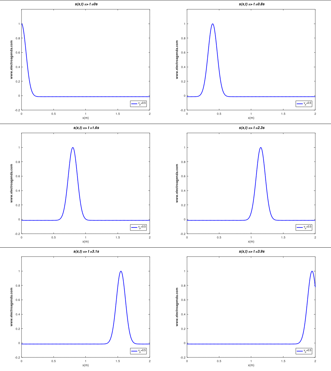
The pulse shown is composed of multiple waves (in practice it has been simulated using 100 waves). The following graph shows the displacement in time of 5 of them, where the axes have been removed to facilitate the visualization:
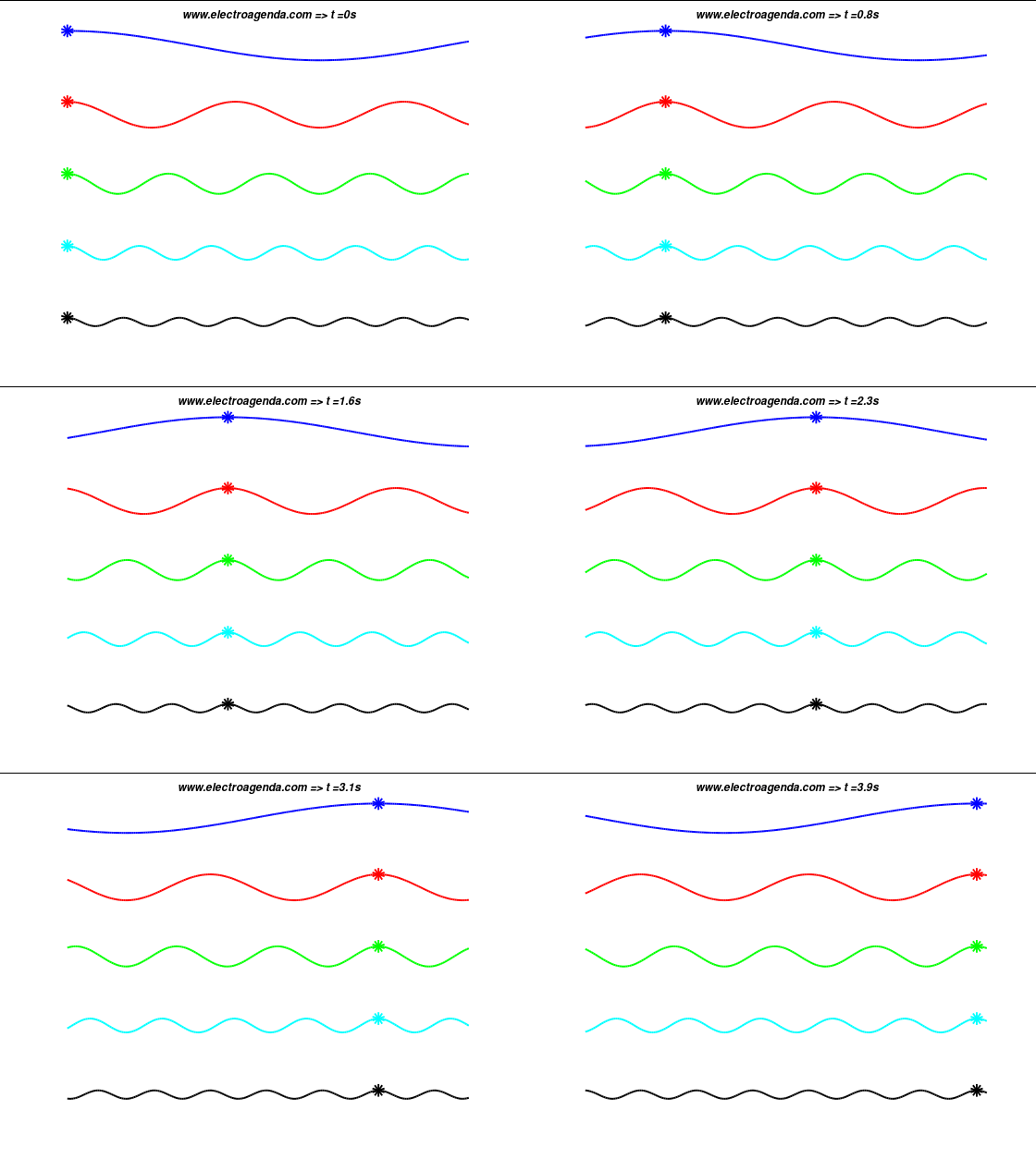
It can be observed how the waves that compose the signal, independent of their frequency and amplitude, propagate at the same velocity. As a result, the Gaussian pulse does not change its appearance, i.e., it is not distorted during propagation.
5. Conclusions
The most important conclusions of this article are:
- Waves are a fundamental concept in electronics and communications theory.
- A wave is a disturbance propagating in a medium, with a typically sinusoidal appearance.
- A simple wave function has two variables: time t and space x. Consequently, it can be represented as a wave at a point over time, or as a wave in space for an instant of time.
- A simple wave is determined by its amplitude A, period T, wavelength λ, wavenumber k, and frequency ω. From the above parameters, the phase velocity at which the wave propagates can be derived.
- Standing waves are produced when waves propagating in opposite directions overlap.
- The signals are composed of multiple waves of different frequencies and amplitudes.
- The transmission media determine the phase velocity of the waves that make up a signal, and the group velocity.
- If there are waves propagating at different phase velocity, the appearance of the original signal is modified.
Bibliography
[1] Wave Propagation and Group Velocity, Léon Brillouin.
[2] Microwave Engineering, David M. Pozar.
[3] RF Circuit Design, Cristopher Bowick.
[4] Communication Systems, A. Bruce Carlson.
Subscription
If you liked this contribution, feel free to subscribe to our newsletter:
