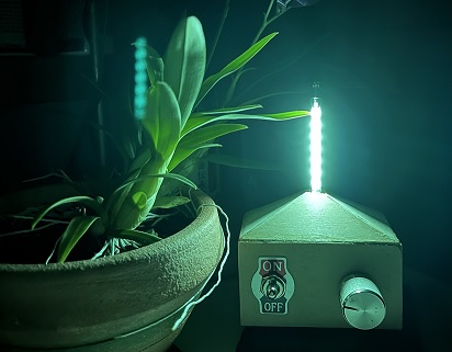
VFD Night Light DIY Project. Developed and written by Frasier Chew.
Vacuum Fluorescent Displays (VFDs) have been around for over 6 decades. Although its heyday has passed in favour of other newer display technologies like the LCD, they are still being used today because of their robustness. VFDs are able to operate under a wide range of temperature conditions and offer exceptional viewing angles.
A simple explanation of how VFDs work is that a cathode filament supplies the electrons which are attracted to phosphor coated anodes. When the phosphor coating is hit by electrons, they fluoresce and emit visible light.
This article is organised as follows. Firstly, section 1 presents and showcases the project. Secondly, section 2 explains how the device is designed and operated. Finally, the annex provides a gallery of pictures, a list of materials and the project code.
1. Description of the Project
1.1 VFD IV-25
In this article, I will show you how I made a cool night light using an old IV-25 Soviet VFD:
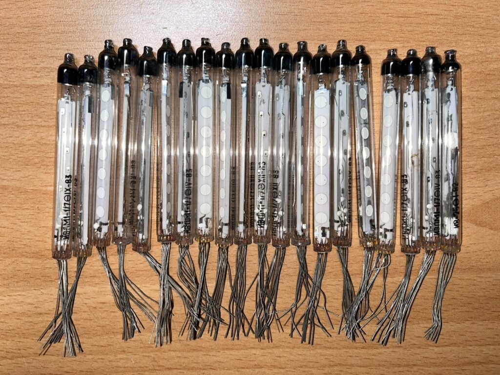
The IV-25 is a 7 segmented bar graph display tube. It is a very simple tube because it has no screen grids and has individual output pins for each anode, making multiplexing unnecessary.
1.2 VFD Night Light
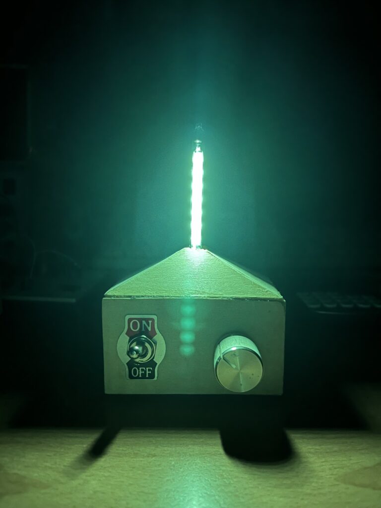
The IV-25 night light is bright enough to illuminate a dark room with a soft green glow. Using the Attiny84, I have coded for 4 different operating sequences for the VFD which is controlled using a rotary selector switch. The whole circuit is powered by a 18650 lithium battery and can be charged with a TP4056 module.
The four modes of operation are:
| Mode 1 | Move from segment to segment, bounce back. |
| Mode 2 | Single segment fade on off, moves upwards then resets. |
| Mode 3 | Full segment illumination, static. |
| Mode 4 | Full segment illumination, pulse fade. |
1.2.1 Mode 1
1.2.2 Mode 2
1.2.3 Mode 3
1.2.4 Mode 4
2. VFD Light Build and Operation
This section shows how the VFD Night Light was designed and built. It includes the following subsections:
- Power supply.
- PCB Schematic and the explanation of the different electronic stages.
- Software.
2.1 Power Supply
2.1.1 Requirements
The Attiny84 microcontroller requires 5Vdc.
Apart from that, in order to use this VFD, 2 different voltages are required:
- 25 Vdc for the anodes
- 2.4 Vac for the cathode filament. Using DC with the filament will result in an unwanted concentration gradient across the VFD tube which can cause uneven illumination of the anode segments. (Section 2.2.1 explains the generation of this voltage)
2.1.2 Voltage Boost Converter
Two MT3608 Boost Converter Modules were used to generate the 25Vdc for the anode segments and the 5Vdc to power the Attiny84 microcontroller:
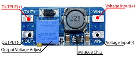
These modules step up the 3.7Vdc from the 18650 battery and provide a constant voltage output which can be adjusted using the potentiometer.
More information about how the MT3608 module works can be found in this link.
2.2 Schematics
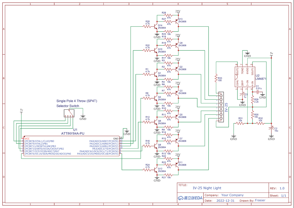
The project schematics can be downloaded from this link. Alternatively, they can be obtained by downloading the following picture:
2.2.1 VFD Filament Supply
For the filament supply, I used the LM4871 audio amplifier IC. This is the modern equivalent of the now obsolete LM9022, a dedicated VFD filament driver IC, but is essentially the same chip. I followed the self-oscillation application circuit to generate pseudo AC using a square wave:
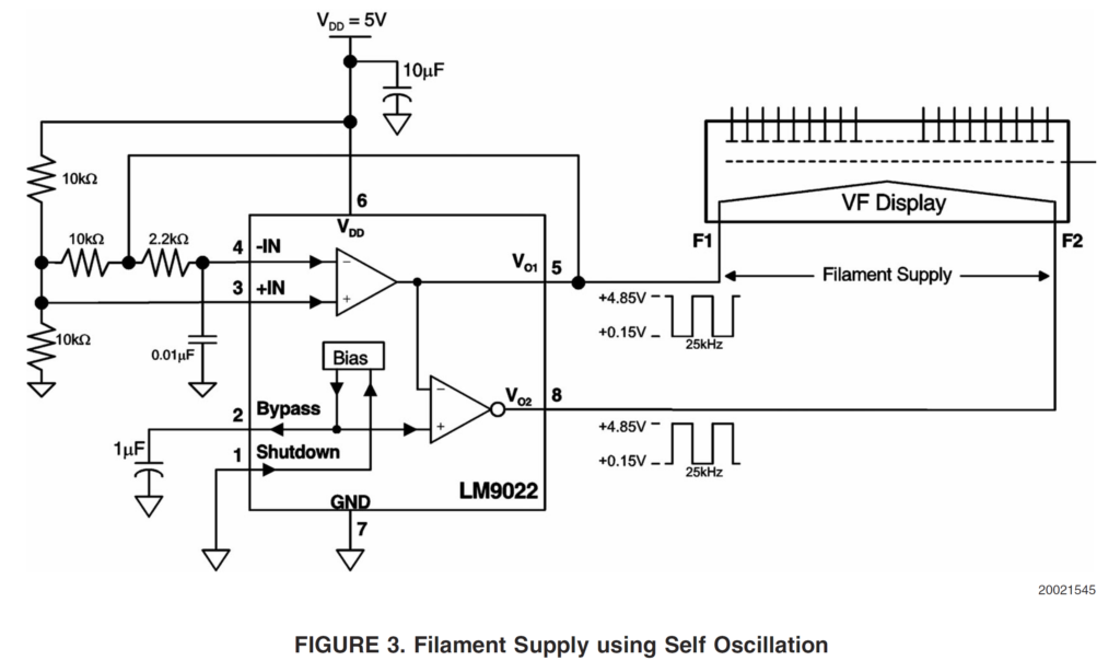
A 100 ohm resistor (R33) was used to limit the current to the filament such that it barely glows. It is important not to overdrive the filament as it will significantly reduce the lifespan of the tube while only marginally increasing brightness.
2.2.2 VFD and Microcontroller Interface
I used Kevin Rye’s circuit design to interface the Attiny84 microcontroller to the VFD. More information about his design can be found here.
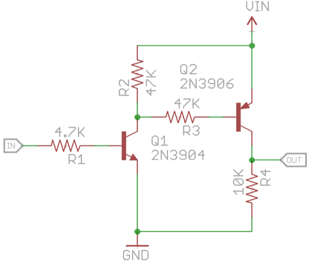
This interface is based on NPN and PNP transistors, namely the references 2N3904 and 2N3906 respectively.
2.2.3 Mode Selection
Because of output port constraints of the Attiny84, I could only code for a maximum of 4 different operating sequences for the VFD. Hence I decided to use a Single Pole 4 Throw (SP4T) rotary switch.
Note If you decide to use a rotary switch with more poles, the extra poles can simply be ignored by not connecting them. So do not worry if you cannot find the exact switch type. You only really need to consider the number of Throws/Positions.
If more sequences are desired, a microcontroller with more I/O pins like the Atmega328 can be used along with other types of switches.
2.3 Software
In order to fade segments on and off, Pulse Width Modulation (PWM) is required. Unfortunately, the Attiny84 does not have enough PWM pins to separately control each of the 7 anode segments hence software PWM is required.
Łukasz Podkalicki has written a code which uses delays in a clever way to pulse fade an LED. The code can be found here. His code works by firstly defining a Max and Min delay value. The Min value is decremented until a condition is met. This triggers “dir = 1” and causes the Min value to Increment until another condition is met which triggers “dir = 0”. “dir” alternates between 1 and 0 creating a pulse fade effect on an LED.
In Annex 3 you can find my Atmel studios code incorporating his software PWM. I highly encourage you to play around with it and create your own operating sequences!
Annex: VFD Night Light Details
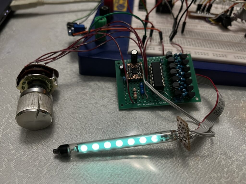
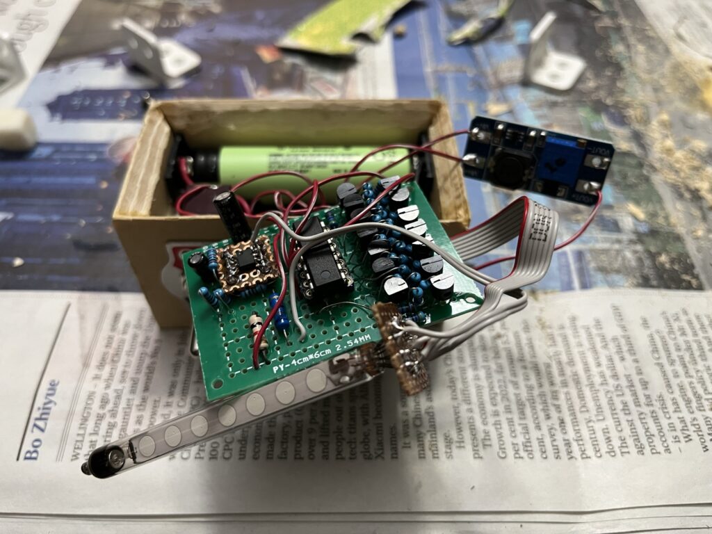
Annex 1: Gallery
Annex 2: List of Materials
| Reference | Number of Units |
| IV-25 VFD | 1 |
| Attiny84 MCU | 1 |
| LM4871 | 1 |
| 2N3904 NPN | 7 |
| 2N3906 PNP | 7 |
| Battery 18650 | 1 |
| ON-OFF Switch | 1 |
| SP4T Rotary Switch | 1 |
| MT3608 Module | 2 |
| TP4056 Charging Module | 1 |
| Resistors | |
| 47K | 14 |
| 10K | 10 |
| 4K7 | 7 |
| 2K2 | 1 |
| 100 | 1 |
| Capacitors | |
| 10 uF Electrolytic | 1 |
| 1 uF Electrolytic | 1 |
| 0.01 uF Ceramic | 1 |
Annex 3: Code
/*
 * IV-25 VFD Night Light.c
 *
 * Created: 15/12/2022 4:33:34 PM
 * Author : Frasier
 */

#include <avr/io.h>
#include <stdio.h>
#define F_CPU 1000000L // 8Mhz internal osc, divided by 8 (fuse)
#include <util/delay.h>

//VFD 7 outputs mapped to PORTA
int seg_1 = 5;
int seg_2 = 4;
int seg_3 = 3;
int seg_4 = 6;
int seg_5 = 0;
int seg_6 = 1;
int seg_7 = 2;

int trigger = 0;

// @@@@@@@@@@ fade code referenced from <blog.podkalicki.com/attiny13-led-fading-with-delay-function/>
//#define DELAY_MAX 512 // value is defined within the for loop itself
#define DELAY_MIN 1
/*
# "Value of DELAY_MAX and DELAY_MAIN should be from range <1, 2^16>"
# "Value of DELAY_MAX should be greater then DELAY_MIN"
*/

/*
Mode 1 - PB0
Move from segment to segment, bounce back.

Mode 2 - PB1
Single segment fade on off, moves upwards then resets

Mode 3 - PB2
Full segment illumination

Mode 4 - PA7
Full segment illumination, pulse fade
*/


int main(void)
{
    // Defining Outputs

	// Enable first 7 ports as Output for VFD segments
	DDRA |= (1 << 0) | (1 << 1) | (1 << 2) | (1 << 3) | (1 << 4) | (1 << 5) | (1 << 6);
	// Enable selector switch Input for mode selection
	DDRA &= ~(1 << 7);
	DDRB &= ~(1 << 0) | (1 << 1) | (1 << 2);

	// Configure pull up resistors
	PORTA |= (1 << 7);
	PORTB |= (1 << 0) | (1 << 1) | (1 << 2);

// @@@@@@@@@@ fade code
	        uint16_t delay = DELAY_MIN;
	        uint8_t dir = 0;


	int count = 0; // counter for break, for Mode 2 pulse

    while (1)
    {

	if( !(PINB & (1 << 0)) ) // if PB0 is pressed, Mode 1
	{
		for (int i = 0; i < 7; i++) // Count upwards
		{
				if( !(PINB & (1 << 1)) ) {trigger = 1;} // if PB1 is pressed set trigger, break out of loop
				if (trigger == 1)
				{
					clear();
					trigger = 0;
					break;
				}
			int a = select(i);
			int b;
			PORTA |= (1 << a); // Turn on segment
			if (i > 0) // turn off the previous segment once "i" is at least 1
			{
				b = select(i-1);
				PORTA &= ~(1 << b); // Turn off segment
			}
			_delay_ms(1000);

			if (i == 6) {PORTA &= ~(1 << seg_7);} // Turn off final segment
		}

		for (int t = 5; t > 0; t--) // Count downwards
		{
				if( !(PINB & (1 << 1)) ) {trigger = 1;} // if PB1 is pressed set trigger, break out of loop
				if (trigger == 1)
				{
					clear();
					trigger = 0;
					break;
				}
			int c = select(t);
			int d;
			PORTA |= (1 << c); // Turn on segment

			if (t < 6)
				{
					d = select(t+1);
					PORTA &= ~(1 << d); // Turn off segment
				}
					_delay_ms(1000);

			if (t == 1) {PORTA &= ~(1 << seg_2);} // Turn off final segment

		}
	}
	if( !(PINB & (1 << 1)) ) // if PB1 is pressed, Mode 2
	{	int DELAY_MAX = 800;
		for (int w = 0; w < 7; w++) // Count upwards
		{
				if( !(PINB & (1 << 0)) | !(PINB & (1 << 2)) ) {trigger = 1;} // if PB0 or PB2 is pressed set trigger, break out of loop
				if (trigger == 1)
				{
					clear();
					trigger = 0;
					break;
				}
			int a = select(w);
			//int b;
			//PORTA |= (1 << a); // Turn on segment

			for (int m = 0; m < 10000; m++)
			{
				if( !(PINB & (1 << 0)) | !(PINB & (1 << 2)) ) {trigger = 1;} // if PB0 or PB2 is pressed set trigger, break out of loop
				if (trigger == 1)
				{
					clear();
					trigger = 0;
					break;
				}

					PORTA &= ~(1 << a); // Turn segment off
					_delay_loop_2(delay);

					PORTA |= (1 << a); // Turn segment on
					_delay_loop_2(DELAY_MAX - delay);

					if (dir)
					{ // fade-in
						if (++delay >= (DELAY_MAX - 1))
						{
							dir = 0;
							count++;
						}
					}
					else
					{ // fade-out
					if (--delay <= DELAY_MIN)
						{
							dir = 1;
						}
					}

					if (count == 1)
					{
						count = 0;
						break;
					}
			}


				PORTA &= ~(1 << a); // Turn off segment


		}
	}
	if( !(PINB & (1 << 2)) ) // if PB2 is pressed, Mode 3
	{
		PORTA |= (1 << 0) | (1 << 1) | (1 << 2) | (1 << 3) | (1 << 4) | (1 << 5) | (1 << 6); // Turn on all segments
		trigger = 1;
	}
	if( !(PINA & (1 << 7)) ) // if PA7 is pressed, Mode 4
	{
		int DELAY_MAX = 1024;

		if (trigger == 1) {
			trigger = 0;
			clear();
		}

		//PORTA |= (1 << seg_3); // compare the brightness of this led, test case
		//PORTA |= (1<<seg_4);

		//@@@@@@@@@@@@@@@ fade code

	clear(); // LED off
	_delay_loop_2(delay);

	PORTA |= (1 << 0) | (1 << 1) | (1 << 2) | (1 << 3) | (1 << 4) | (1 << 5) | (1 << 6); // Turn all segments on
	_delay_loop_2(DELAY_MAX - delay);

	if (dir) { // fade-in
		if (++delay >= (DELAY_MAX - 1)) dir = 0;
	}
	else { // fade-out
	if (--delay <= DELAY_MIN) dir = 1;}


	}

    }
}

// Function for mapping the segment outputs in the correct order
int select(int a) {
	if (a == 0){return seg_1;}
	if (a == 1){return seg_2;}
	if (a == 2){return seg_3;}
	if (a == 3){return seg_4;}
	if (a == 4){return seg_5;}
	if (a == 5){return seg_6;}
	if (a == 6){return seg_7;}
}

void clear() { // Function for clearing all the segments
	PORTA &= ~(1 << 0);
	PORTA &= ~(1 << 1);
	PORTA &= ~(1 << 2);
	PORTA &= ~(1 << 3);
	PORTA &= ~(1 << 4);
	PORTA &= ~(1 << 5);
	PORTA &= ~(1 << 6);
}
Subscription
If you liked this contribution, feel free to subscribe to our newsletter:
