The envelope of a bandpass signal represents the signal, typically baseband, that served as the modulator of the carrier frequency. Although the power of the resulting signal may vary with time, its value can be generalized as a function of the envelope amplitude.
The following text shows the evolution from the calculation of the power of a sinusoid to the calculation of the power of a generic bandpass signal as a function of the envelope.
The table of contents is as follows:
1. Periodic Power Signals
This text focuses on the context of power bandpass signals [1]. Power signals are extended in time providing energy permanently, but with a limited power value.
Given a periodic power signal s(t) with period T, the average power P is defined as the root mean square value over a period:
\begin{equation} P = \cfrac{1}{T} \int_0^T s^2(t)dt \end{equation}
Note that an analogy can be established between the previous power P of a theoretical signal and the power obtained in an electronic circuit. According to Circuit Theory [2], the power PR generated by a voltage v(t) equal to s(t), and its corresponding current i(t) in a resistor R, is equal to:
\begin{equation} P_R= \cfrac{1}{T} \int_0^T v(t)i(t)dt = \cfrac{1}{RT} \int_0^T v^2(t)dt = \cfrac{P}{R} \end{equation}
In summary, both powers are equal for a normalized resistance R=1.
2. Signal Envelope
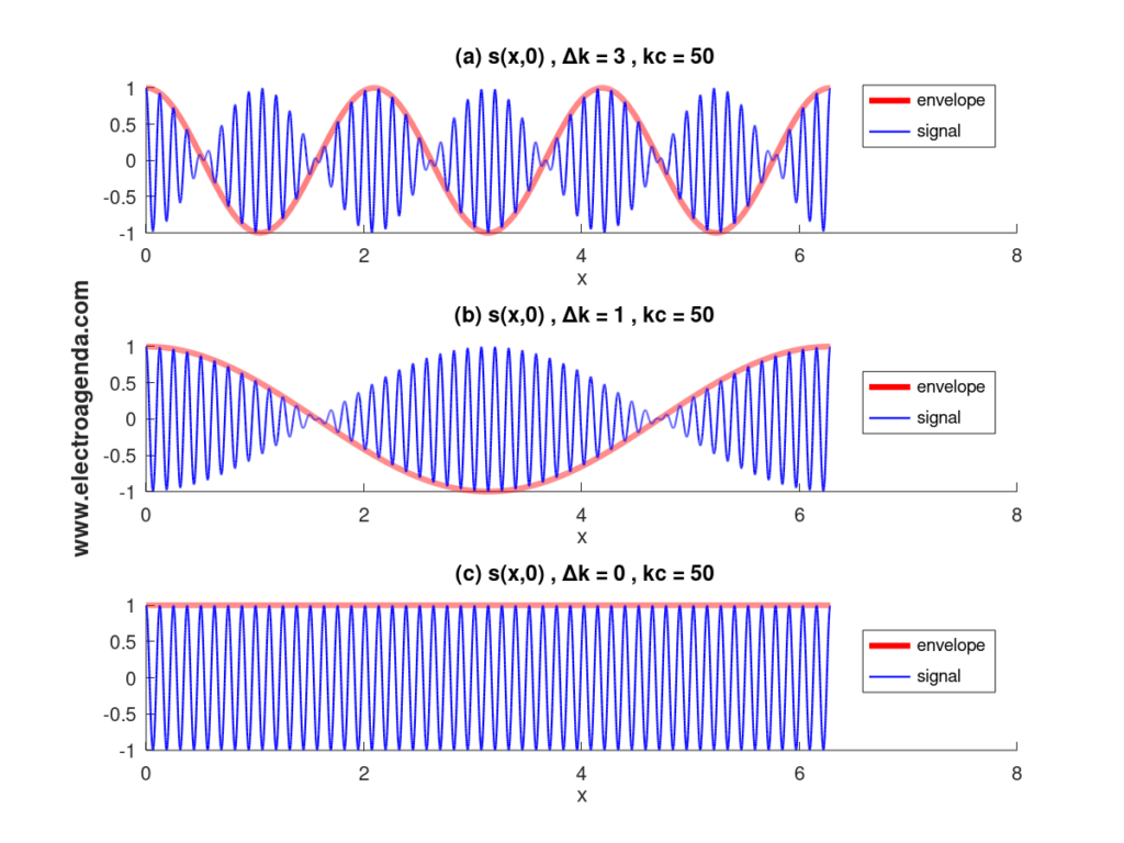
The following graph, taken from our explanation of group velocity, shows several simple examples of bandpass signals and their corresponding envelopes.

The graph shows signals throughout space at an instant of time. For the rest of the text, time signals at a point in space will be considered equivalently and without loss of generality.
2.1 Constant Envelope Sinusoid
The simplest case, a sinusoid of constant amplitude A and constant envelope, is considered below:
\begin{equation} s(t) = A\cos(\omega t) \end{equation}
The graphical representation corresponds to case (c) in the previous image.
Applying equation (1), and after several simple trigonometric manipulations, a constant power value is obtained:
\begin{equation} \begin{split} P &= \cfrac{1}{T} \int_0^T s^2(t)dt \\ &= \cfrac{A^2}{T} \int_0^T \cos^2(\omega t)dt \\ &= \cfrac{A^2}{2T} \int_0^T [1+\cos(2\omega t)]dt \\ &= \cfrac{A^2}{2} \end{split}\end{equation}
The last step occurs because the integral of a sinusoid over an integer number of periods is equal to zero.
Next, it is shown that this result can be extrapolated to the power of a bandpass signal with generic envelope.
2.2 Generic Envelope
2.2.1 Power Calculation
Any bandpass signal s(t) can be written as a function of its in-phase, i(t), and quadrature, q(t) components [1]. Mathematically:
\begin{equation} s(t) = i(t)\cos{\left(\omega_c t \right)} + q(t)\sin{\left(\omega_c t \right)} \end{equation}
Due to the evolution of the amplitudes of i(t) and q(t), the signal power can vary in time. Applying equation (1), and taking into account that the period T of the carrier is constant, it is obtained that:
\begin{equation} \begin{split} P(t) &= \cfrac{1}{T} \int_t^{t+T} s^2(t)dt \\ &= \cfrac{1}{T} \int_t^{t+T} [i^2(t)\cos^2(\omega t) + q^2(t)\sin^2(\omega t) + 2i(t)q(t)\cos(\omega_c t)\sin(\omega_c t)]dt \end{split}\end{equation}
To advance in the calculations, the following reasoning must be performed. First, both i(t) and q(t) are baseband signals. Second, if the carrier frequency is sufficiently high, i(t) and q(t) can be considered constant over a period T. Consequently, equation (6) can be solved as follows:
- By analogy with (4), the first integral will be equal to the square of i(t) divided by two.
- By analogy with the previous point, the second integral will be equal to the square of q(t) divided by two.
- Applying basic trigonometry, the third integral is equivalent to the integral of a sinusoid with frequency twice the carrier. And, again by analogy with (4), it will be equal to zero.
In summary, it is obtained that:
\begin{equation}P = \cfrac{i^2(t) + q^2(t)}{2} \end{equation}
2.2.2 Power to Envelope Ratio
From the analysis of the analytic signal and the complex envelope of s(t), it is shown that its envelope e(t) is equal to:
\begin{equation} e(t) = |s_{a\downarrow}(t)| = \sqrt{i^2(t) + q^2(t)} \end{equation}
Therefore, from (7) and (8), it follows that:
\begin{equation} P = \cfrac{e^2(t)}{2} \end{equation}
Thus the analogy between equations (4) and (9) is obtained. Given a bandpass signal, the instantaneous envelope is given by the modulus of the signal in the complex plane:
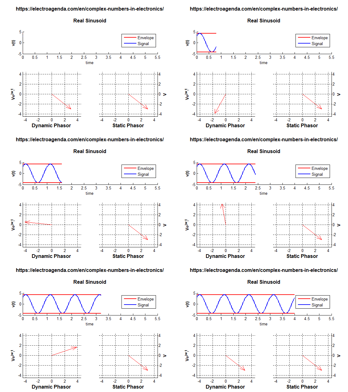
- In the case of a sinusoid, this envelope is always constant, as shown in the following graph:

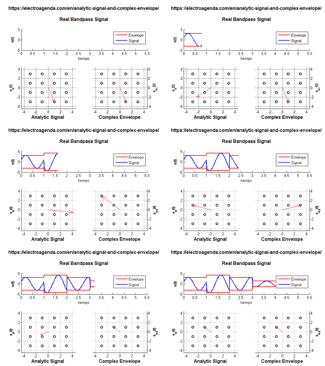
- In a signal with in-phase and quadrature components, the instantaneous envelope is a consequence of both components, as reflected in the following example (for simplicity, the center frequency has been reduced and the transitions between symbols have been eliminated):

Once the envelope has been determined, in all cases the instantaneous power is obtained with equation (9).
3. Conclusions
The text can be summarized in the following concepts:
- The power of a bandpass signal evolves in direct proportion to its envelope.
- The envelope of a simple sinusoid is its amplitude.
- The envelope of a more complex bandpass signal is obtained directly from its in-phase and quadrature components.
- The complex plane allows simultaneous display of the in-phase and quadrature components together with the instantaneous envelope of the signal.
Bibliography (Sponsored)
[1] Communication Systems, A. Bruce Carlson.
[2] Electric Circuits, James Nilsson.
Subscription
If you liked this contribution, do not hesitate to subscribe to our newsletter:
