3.2 Analog Electronics
This section explains in a basic way the fundamental concepts on which Analog electronics is based, reviewing the most important components and specialties.
3.2.1 Fundamentals
3.2.1.1 Voltage (v) and Current (i)
Electronic engineers design circuits to solve problems and / or needs. This work is done by completely abstracting from the electrons. Instead we work with two manifestations that are produced by the flow of these charges: voltage (v), and current (i).
A voltage of v volts (V) is a quantity that represents the potential difference between two points. Strictly, it indicates the work required per unit charge to move a charged particle between the two points. A current of i amps (A) implies a flow of charges, such as electrons, circulating through a conductive element.
These concepts seem complicated and in fact they are. To explain them well, we would have to delve into the field of electromagnetism [1] [2]. However, this is not necessary to understand electronics in a basic way. Simplifying: for any generic circuit, there are one or more input voltages and currents, whether they are from the mains supply, from a battery or cell, from a signal from another circuit, generated by a sensor… and the electronics designer is in charge of devising a circuit that transforms those input voltages-currents into other output voltages-currents that allow the desired function of the circuit to be fulfilled. This typically complex task requires a command of the components and theories discussed below.
3.2.1.2 Meaning of “Analog”
The word “analog”, applied to the field of electronics, means that the voltages / currents that occur in any node of a circuit have a continuous, and therefore infinite, range of values. This is not equivalent to say that the maximum and minimum values of a given voltage / current are not delimited.
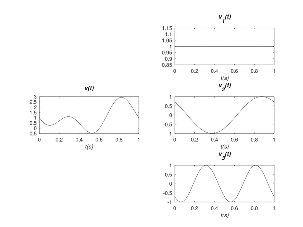 |
This concept becomes clearer with a practical case. In Figure 1, on the left, a voltage measured across an element of a circuit is observed over time v(t). The range of values is limited to between -0.5 and 3 volts approximately. However, the signal can acquire any value within that range. For example: 1 V, 1.1 V, 1.01 V, 1.001 V, etc. In practice, the voltage values read will be limited by the resolution of the measuring instrument. But the key is that in an analog signal there is no degree of discretization or limitation in the voltages and currents. They can potentially have any value.
Examples of analog signals would be the output voltage of a temperature sensor, or analog radio and television signals. Actually, any signal measured in a real circuit is always analog. This statement will be deepened below.
3.2.1.3 Frequency and Phase
Any signal (voltage or current) in a circuit is composed of a continuous part and / or an alternating part. Typically the acronyms DC (direct current) are used for the continuous part, and AC (alternating current) for the alternating part. For example, returning to Figure 1, the signal v(t) is composed of the sum of the signals v1(t) + v2(t) + v3(t). The first component has a continuous value and constitutes the DC of the signal, while the second and third components have an alternating value and constitute the AC.
In this way, it can be generalized that any signal is composed of different frequency components or, directly, frequencies. Continuing with Figure 1, the signal v1(t) is the DC or zero frequency. The rest of the AC components have certain frequencies. Frequency indicates the number of times a periodic tone is repeated in one second (s) and is measured in Hertz (Hz). Therefore v2(t) and v3(t) have frequencies of 1 Hz and 2 Hz respectively. Likewise, each frequency component has a phase. The phase indicates the deviation of the peak of the tone with respect to the origin of times (t=0 typically), and is expressed in angular measures. It is clear that in our example v2(t) and v3(t) have different phases. As a final conclusion, it can be stated that the signals are defined by the amplitudes and phases of the frequencies that compose them.
3.2.2 Circuit Theory
Circuit Theory [3] is necessary to calculate the voltage and the incoming / outgoing currents at any node of an electrical circuit. Circuit Theory is based on two axes. First of all, fundamental laws that must be observed in any circuit. The most basic are Ohm’s Law [4] and Kirchhoff’s Laws [5], the explanation of which is beyond the scope of this text. Second, the “laws” or equations that define the behavior of each electronic component that is part of the circuit. The most used components, which are briefly explained below, are: resistors, capacitors, coils or inductors, diodes, and transistors.
3.2.2.1 Passive Component
Passive components respond to current flow by dissipating or storing energy. Unlike active ones, they cannot control the flow of current or amplify the power of a signal. The most basic two-terminal passive components are:
- Resistors: they hinder the passage of current dissipating energy. They respond the same to all frequencies. The resistance value is measured in ohms (Ω).
- Capacitors: they store energy by accumulating charge and generating an electric field between their terminals. This load can be delivered to the rest of the circuit if conditions require it. For low frequencies they tend to behave like an open circuit (disconnection between their terminals) and for high frequencies like a short-circuit (direct connection between their terminals). Ideally they do not dissipate / lose energy. Its capacity value is measured in Farads (F).
- Coils/inductors: they are complementary to the capacitor. They store energy in a magnetic field between their terminals. For high frequencies they tend to behave like an open circuit (disconnection between their terminals) and for low frequencies like a short-circuit (direct connection between their terminals). Ideally they do not dissipate / lose energy. Its inductance value is measured in Henries (H).
In practice there are no pure resistors, capacitors or coils. Inherently, all components present parasite effects that limit their quality. Thus any real passive component is a combination of all three. These parasitic effects must be taken into account, because they can mean limitations and/or bottlenecks in electronic designs.
Table 2 illustrates typical symbols for these components on electronic circuit schematics. Images of real discrete units are also shown for each component, both with pins for manual mounting and SMD (“Surface Mounted Device”) for automatic surface mounting.
|
Resistors |
Capacitors |
Coils / Inductors |
|
|
Electric Symbol |
|
|
|
|
Discrete Examples |
|
|
|
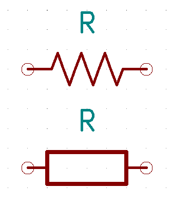
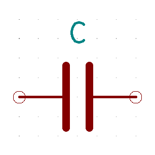
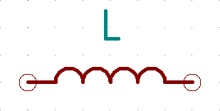
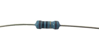
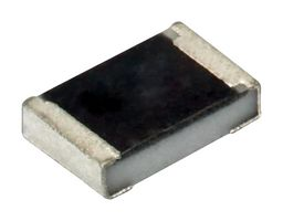
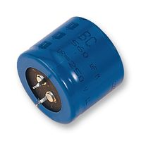
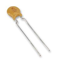
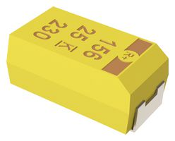
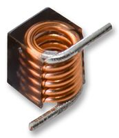
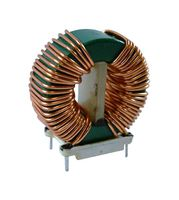
Table 2: Symbols and Examples of passive components.
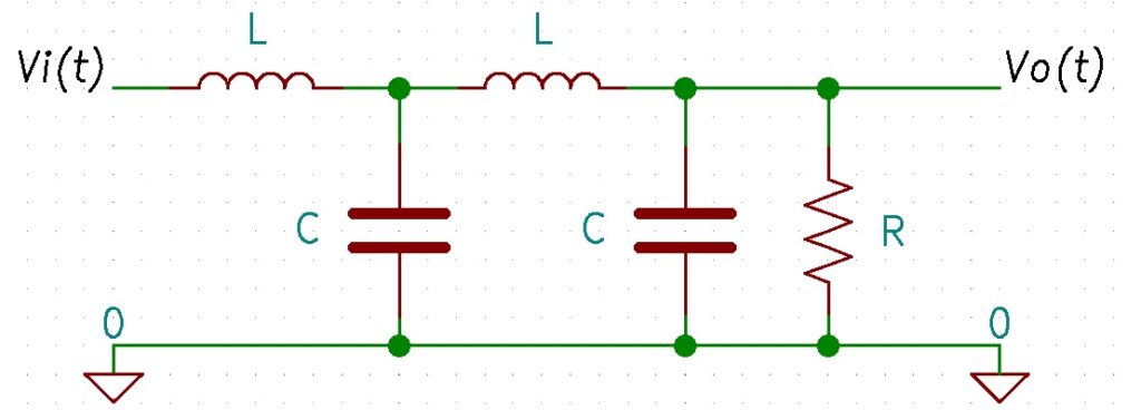
Finally, Figure 2 shows an example of an electrical scheme with passive components. Using the values of each component and circuit theory one could calculate voltages / currents at each node / branch for any input drive vi(t). In this case, the circuit tends to behave like a low-pass “filter”, since the output vo(t) reduces the amplitude of the high-frequency components that may be present in vi(t).
 |
3.2.2.2 Active Components
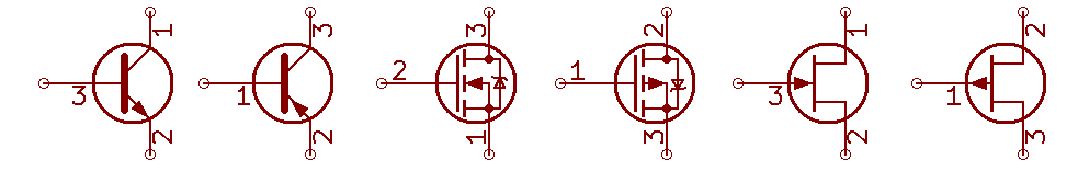
Unlike passive components, active components have semiconductor junctions that give them important properties. The most important is that they can exert control over the flow of the current. In practice this means that they can act as solid state switches (semiconductor, without electromechanical parts) and as power amplifiers. The most commonly used active components are diodes and transistors. Diodes have two terminals while transistors have three.
Typical electrical symbols for diodes and transistors are illustrated in Table 3. The latter can be very different because there are many manufacturing technologies, so only several options are illustrated. Example pictures of discrete components are also shown, both hand-mounted and SMD.
|
Diodes |
Transistors |
|
|
Electric Symbol |
|
|
|
Discrete Examples |
|
|
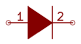

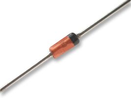
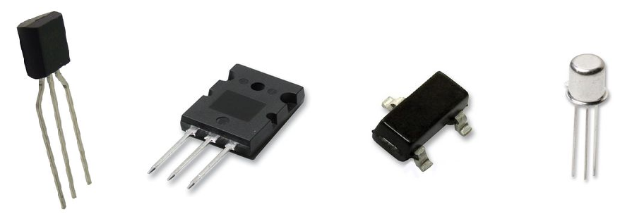
Table 3: Schematic symbols and discrete examples of active components.
Finally, to represent the relevance of transistors, Figure 3 shows two applications that would be impossible to perform using only passive components: a power amplifier and an inverter / switch. The circuits are not shown in detail because they are outside the scope of this text. On the left, a signal with an instantaneous input power pi(t) is represented, which is amplified obtaining a power greater than the output of the circuit po(t). On the right, the inverter is seen, since a high input voltage translates into a low output voltage and vice versa. This behavior can be achieved by consuming energy only in the transition between the two states, which emphasizes the suitability of the transistor to implement digital circuits (more on this later).
 |
3.2.3 Other Specializations
A fundamental and necessary element for the correct operation of any electronic circuit is the power supply. For example, any device connected to the electrical network (AC signal of 50 Hz in Europe and 60 Hz in the United States) usually requires a conversion of this AC voltage into DC to power the internal circuits. The specialty that studies the use of solid state devices (semiconductors) for the control and conversion of electrical power is called Power Electronics [6].
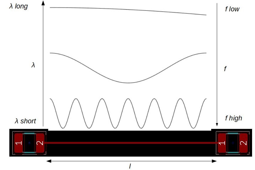
Another very important specialty is Radio-Frequency (RF) Electronics or Microwave Engineering [7] [8]. Any AC tone that propagates in a medium has an associated wavelength λ. The higher the frequency f, the smaller the associated value of λ. This is illustrated in Figure 4 where a track of length l is seen separating any two components. If λ is long enough (low frequency) compared to l, the transmission of the signal (v(t) or i(t)) is considered instantaneous and conventional Circuit Theory can be used to study the circuit. In other words, the electrical diagram uniquely determines the operation of the circuit. On the other hand, if λ is short (high frequency) compared to l, the basic circuit theory is not applicable because it is necessary to take into account the transmission or propagation of the signal between both points. In these cases it is necessary to use RF and Microwave electronics. It is the physical arrangement of the components and the transmission lines that link them what determines the operation of the circuit. In other words, things get a lot more complicated because the difference between a design that works and one that doesn’t can be 1 millimeter.
 |
Note that the concept of “microwave” has become very popular for coining the name of the appliance that is used to heat food. Indeed, this device uses microwave frequencies to excite and heat the molecules that make up food. However, the professionals who are dedicated to Microwave Engineering are dedicated in their vast majority to the design of equipment, devices and components of high frequency communications or similar.
Bibliography (Sponsored)
[1]: Cheng, David, Field and Wave Electromagnetics, 2020.
[2]: Fleisch, Daniel, A Student’s Guide to Maxwell’s Equations, 2008.
[3]: Nilsson, James, Electric Circuits, 2019.
[4]: Wikipedia, Ohm´s Law.
[5]: Wikipedia, Kirchhoff’s circuit laws.
[6]: Mohan, Ned, Power Electronics: Converters, Applications, and Design, 2002.
[7]: Bowick, Cristopher, RF Circuit Design, 2007.
[8]: Pozar, David M., Microwave Engineering, 2011.
Subscription
If you liked this contribution, feel free to subscribe to our newsletter: