
Optical modulators use electrical signals to modify the physical characteristics of materials in such a way that the propagation conditions of light change. This article explains the most common optical modulators that are widely employed in optical communications. Firstly, Electro-Absorption Modulators are briefly describred. Secondly, electro-optic Mach-Zehnder Modulators (MZM) are introduced. Finally, the most relevant mathematical principles of the MZMs are emphasized.
The text is organized as follows:
1. Electro – Absorption Optical Modulators
Electro-Absorption Modulators (EAM) are optical modulators based on the Franz–Keldysh effect. An electric field can be applied to a semiconductor modifying the bandgap energy between two bands ΔE. If the incoming lightwave presents photons with a lower energy (hν < ΔE), the semiconductor will be transparent. If the incoming energy is higher than the bandgap (hν > ΔE), absorption will occur as illustrated in this link. With this approach, an electrical signal can be employed to modulate the power of the output lightwave.
EAMs can be integrated in the same package with a laser, in a structure known as Externally Modulated Laser (EML). EMLs achieve low voltage operation, high bandwidth and reduced chirp. The main disadvantage of EAMs is that they cannot perform phase modulation. This limitation impedes not only the use of EAMs in coherent systems, but also the direct generation of Optical Single Side Band (OSSB) signals that rely on the Hilbert Transform.
2. Electro-Optic Mach-Zehnder Optical Modulators
2.1 Fundamentals
2.1.1 Electro-Optic Effect
The electro-optic effect, also known as Pockels effect, consists of a linear variation in the refractive index of crystals induced by an electric field. A change in the refractive index translates into a change in the propagation speed of light in the material. A single waveguide in which the speed of light varies according to an electric signal achieves optical phase modulation. Furthermore, this concept is also employed along with Mach-Zehnder interferometers to obtain phase and amplitude modulation of light dependent on an electrical signal.
2.1.2 Structure
Next figure shows the principle of operation of a Mach-Zehnder Modulator (MZM). The power of an incident lightwave splits into two equal signals that propagate through waveguides under the effect of a varying electric field. The associated modification of the refractive index produces a relative phase shift between the two lightwaves. When they recombine, any level of interference, from destructive to perfectly constructive, is possible and depends on the applied electrical signal.
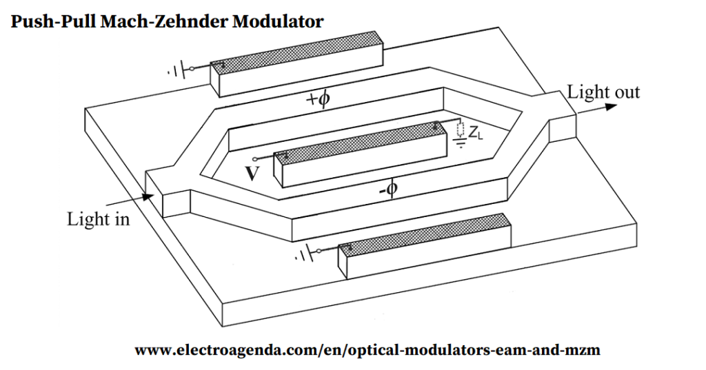
The figure above shows a push-pull MZM where the two waveguides suffer opposite phase shifts, +ϕ and -ϕ. This structure is preferred because it can halve the required voltage to obtain any value of relative phase shift. Different configurations of optical modulators exist, but in general they all can be reduced to a combination of phase modulators and/or MZMs.
2.2 Transfer Function
The transfer function of an ideal MZM will be derived mathematically and illustrated, showing both the output electric field and power. Then, the relevance of the bias point will be discussed.
2.2.1 Mathematical Development
2.2.1.1 Electric Field
As an starting point, the electric field of the optical incoming signal is a lightwave generated by a laser:
\begin{equation} E(t) = E_i\cos(\omega_ct) \end{equation}
Initially, it is divided into two equal power carriers E1(t) and E2(t) with a 3dB splitting ratio with respect to the original:
\begin{equation} E_1(t) = E_2(t) = \cfrac{E_i}{\sqrt{2}}\cos(\omega_ct) \end{equation}
The carriers propagate in two different waveguides that suffer an opposite relative phase shift. A figure of merit of any MZM is the half wave voltage Vπ, and it determines the required voltage to generate an overall relative phase shift equal to π radians. Thus, the phase shift that is produced in any arm of the MZM due to a voltage V is:
\begin{equation} |\phi| = \cfrac{\pi V}{2V_{\pi}} \end{equation}
Consequently, once both lightwaves are combined again, the electric field at the output of the MZM can be written as:
\begin{equation} E_o(t) = \cfrac{E_i}{2}\cos\left(\omega_ct + \cfrac{\pi V}{2V_{\pi}}\right) + \cfrac{E_i}{2}\cos\left(\omega_ct - \cfrac{\pi V}{2V_{\pi}}\right) \end{equation}
Note that each carrier presents an additional 3 dB loss due to the power combiner loss (otherwise there would be more power at the output of the MZM than at the input).
Applying the equality:
\begin{equation} \cos(A)\cos(B) = \cfrac{1}{2}\left[\cos\left(A + B\right) + \cos\left(A - B\right) \right] \end{equation}
Equation (4) can be rewritten as:
\begin{equation} E_o(V,t) = E_i\cos\left(\cfrac{\pi V}{2V_{\pi}}\right)\cos\left(\omega_ct\right)=E_p(V)\cos\left(\omega_ct\right)\end{equation}
Where the peak amplitude of the electric field has been expressed as Ep(V), as it depends on V. Note that Ep(V) also carries phase information, as it can be positive or negative.
2.2.1.2 Optical Power
The associated power of Eo(V,t)is equal to the average power for the optical frequencies. Similarly to the procedure presented in this link:
\begin{equation} P_o(V) = \langle E_o^2(V,t) \rangle = \cfrac{E_p^2(V)}{2}=\cfrac{E_i^2}{4}\left(1+\cos\left(\cfrac{\pi V}{V_{\pi}}\right)\right) \end{equation}
2.2.2 Graphical Representation
The transfer function of the MZM, for Po(V) and Ep(V), is illustrated in the figure below normalising Ei=1.
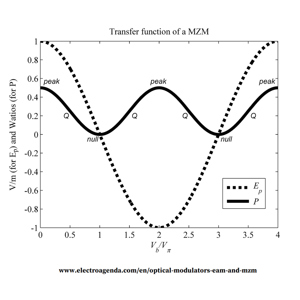
It is clear that a MZM is a nonlinear device, although this impairment can be overcome employing the appropriate level in the driving electrical signals, as explained next.
2.2.3 Bias Point
2.2.3.1 Definition
The applied voltage V can be composed of two elements: a DC component Vb, that defines the bias of the device, plus an AC signal s(t) with the information to transmit:
\begin{equation} V = V_b + s(t) \end{equation}
The bias point establishes the initial level from which Po(V) and Ep(V) will vary according to the modulating signal s(t). From the point of view of the output power, there are three types of important bias points that repeat periodically: peak, null and quadrature (Q). These points can be found at Vb/Vπ=2n, Vb/Vπ=2n+1, and Vb/Vπ=n+0.5 respectively, with n being any integer number.
2.2.3.2 Optimization
The best bias point depends on the physical parameter that will carry the information and will be detected in the receiver.
2.2.3.2.1 Intensity Modulation
For intensity modulation, the most linear point is quadrature. This concept can be deduced visually from the power curve in Figure 2.
The mathematical justification can be performed expanding equation (7) with the V provided in equation (8). Considering quadrature at Vb/Vπ=1.5, a modulating signal s(t) with a peak amplitude very small in comparison with Vπ, and applying sin(x)≈x for small values of x, an approximately linear modulation can be achieved:
\begin{equation} \begin{split} P_o(t) &=\cfrac{1}{4}\left(1+\cos\left(\cfrac{3\pi}{2}+\cfrac{\pi s(t)}{V_{\pi}}\right)\right)\\&=\cfrac{1}{4}\left(1+\sin\left(\cfrac{\pi s(t)}{V_{\pi}}\right)\right)\\&\approx \cfrac{1}{4}\left(1+\cfrac{\pi s(t)}{V_{\pi}}\right)\end{split} \end{equation}
Without applying any approximation, the higher the amplitude of s(t), the higher the intermodulation products at the output. Note that in this case, the transmitted power belongs mostly to the optical carrier instead of the information signal.
2.2.3.2.2 Coherent Modulation
In coherent systems, information is transmitted in the phase and/or the amplitude of the electrical field Eo(t). In that case, the optimum bias point is null, as it can be visually deduced from Figure 2.
Again, a mathematical justification can be provided expanding Ep(V) in equation (6) with the V provided in equation (8). Considering null at Vb/Vπ=3 and a peak amplitude of s(t) very small in comparison with Vπ, the signed peak of the electric field is:
\begin{equation} \begin{split} E_p(t) &=\cos\left(\cfrac{3\pi}{2}+\cfrac{\pi s(t)}{2V_{\pi}}\right)\\&= \sin\left(\cfrac{\pi s(t)}{2V_{\pi}}\right) \\&\approx \cfrac{\pi s(t)}{2V_{\pi}} \end{split} \end{equation}
Note that in this case there is no power lost in the transmission of the optical carrier. That benefit is achieved at the expense of requiring a coherent receiver, much more complicated than a power detection receiver.
2.3 MZM Summary
To summarise, MZMs can achieve phase and intensity modulation of optical carriers. Accordingly, they can generate OSSB signals directly. Moreover, they present higher modulation bandwidths than conventional lasers and can operate free of phase and frequency chirp. The main disadvantage is the nonlinear behaviour, although it can be balanced with a proper analysis on the optimum configuration according to the desired modulating signals.
Bibliography (Sponsored)
[1] Fiber-Optic Communication Systems, Govind P. Agrawal
[2] Broadband Optical Modulators, Antao Chen
[3] Semiconductor Optical Modulators, Koichi Wakita
Subscription
If you liked this contribution, feel free to subscribe to our newsletter: