DIY Audio Equalizer Developed and Written by Gabriel Dantas.
This article was written by a beginner for beginners in electronics. My name is Gabriel, and I am studying Electrical Engineering at the University of Brasilia (currently in my fifth semester). The objective is to share my learning process and mistakes while building a cheap, simple equalizer – my first experience with analog filters.
It is important to note that this is not a hi-fi (high-fidelity) audio device; the focus here is to understand the basics behind audio filters and their applications. It was a challenging but incredibly rewarding process for me as a student.
Additionally, this project was summarized in a 2-minute and 40-second video that you can find at the end of the text. Furthermore, I would like to thank Gabriel S. Vera for reviewing the English in this text.
The text is organised as follows:
1. Equalizer Design
1.1 Analog Filters
To understand how an equalizer works, it is essential to know what analog filters are and how they function. An analog filter is a circuit that processes electrical signals to attenuate or allow certain frequency ranges. It is built using components such as resistors, capacitors, inductors, and operational amplifiers.
1.1.1 Classification
1.1.1.1 Topology
In this project, we will use the three most common filters:
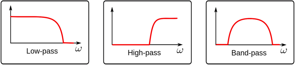
- Low-Pass Filter: Allows low frequencies and attenuates high frequencies (used as a bass booster);
- High-Pass Filter: Allows high frequencies and attenuates low frequencies (used as a treble booster);
- Band-Pass Filter: Allows a specific range of frequencies and attenuates the others (used as a midrange booster).
The idea of an equalizer is to combine these filters into a single signal and allow their gain to be adjustable. With this, we can control the attenuation or amplification of low, high, and midrange frequencies.
1.1.1.2 Active and Passive Filters
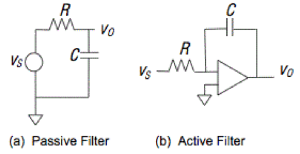
Now that we understand what filters are, we need to choose between active and passive filters.
Active filters include active components like operational amplifiers (op-amps), transistors, or other active devices, along with resistors and capacitors. They require an external power supply and can amplify signals, provide better impedance matching, and allow for more precise control of frequency response.
Passive filters are built using only passive components such as resistors, capacitors, and inductors. They do not require an external power source and cannot amplify signals. However, inductors can make them bulky and sensitive to electromagnetic interference.
To reduce electromagnetic interference, I decided to assemble my project using active filters.
1.1.1.3 Filter Orders
Based on this, we now have to decide the order of our filter.
The order of a filter refers to the number of reactive components (capacitors or inductors) that determine the filter’s frequency response. It directly affects the attenuation slope beyond the cutoff frequency. This is extremely important when designing filters because it determines how quickly the system will cut off a specific frequency range.
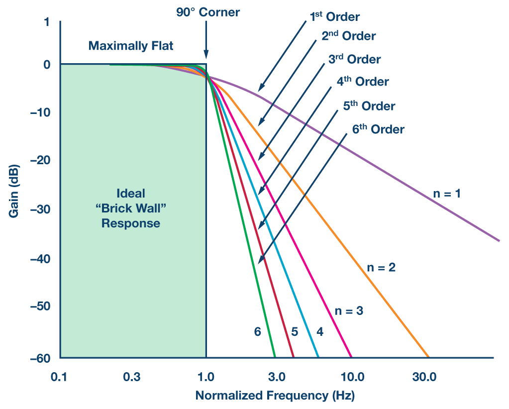
However, since we are assembling a three-channel equalizer, the filter order does not need to be high. Given that we have only three bands with a relatively broad frequency range, a first-order filter will be more than sufficient to separate low, high, and midrange frequencies.
1.1.2 Cut-Off Frequency
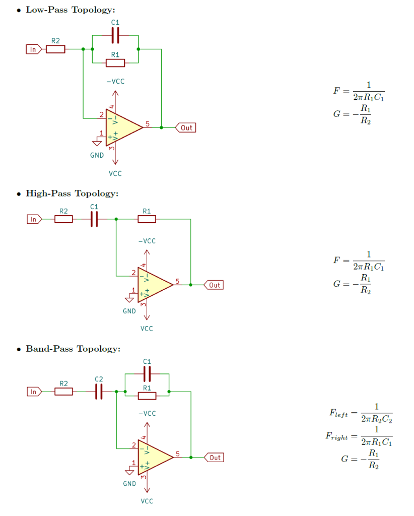
To assemble the filters, I chose a first-order topology, that is one of the most well-known and is exactly the one I learned in college when I first started thinking about this project.
1.1.2.1 Theoretical Values
Below, I present low-pass, high-pass, and band-pass filters using this topology, along with the equations to determine each cutoff frequency and gain. These equations can be derived by calculating the transfer function of the filter.
1.1.2.2 LT Spice Simulations
Based on the equations, I calculated the desired cutoff frequencies for each filter and visually analyzed the graph in LTspice software. I made small adjustments to the capacitor values to fine-tune the cutoff frequencies so that the three filters would visually occupy their respective bands. Below, the simulated response curves of each filter are also shown.
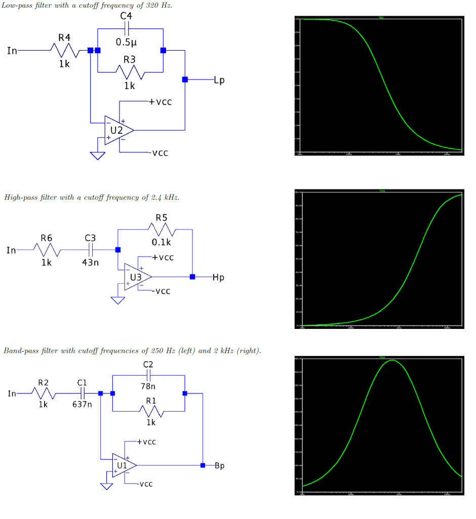
The selected cut-off frequencies can be observed in the picture.
1.1.3 Gain
1.1.3.1 Adding Channels
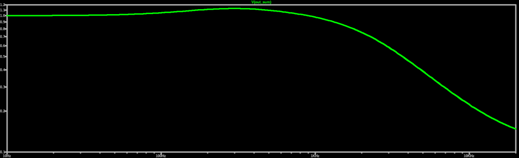
Thus, I summed the three signals using an inverting summing amplifier and adjusted the weight of each signal to suppress the effects of natural overlaps between the filter curves. I did this by testing values that resulted in the flattest possible signal.
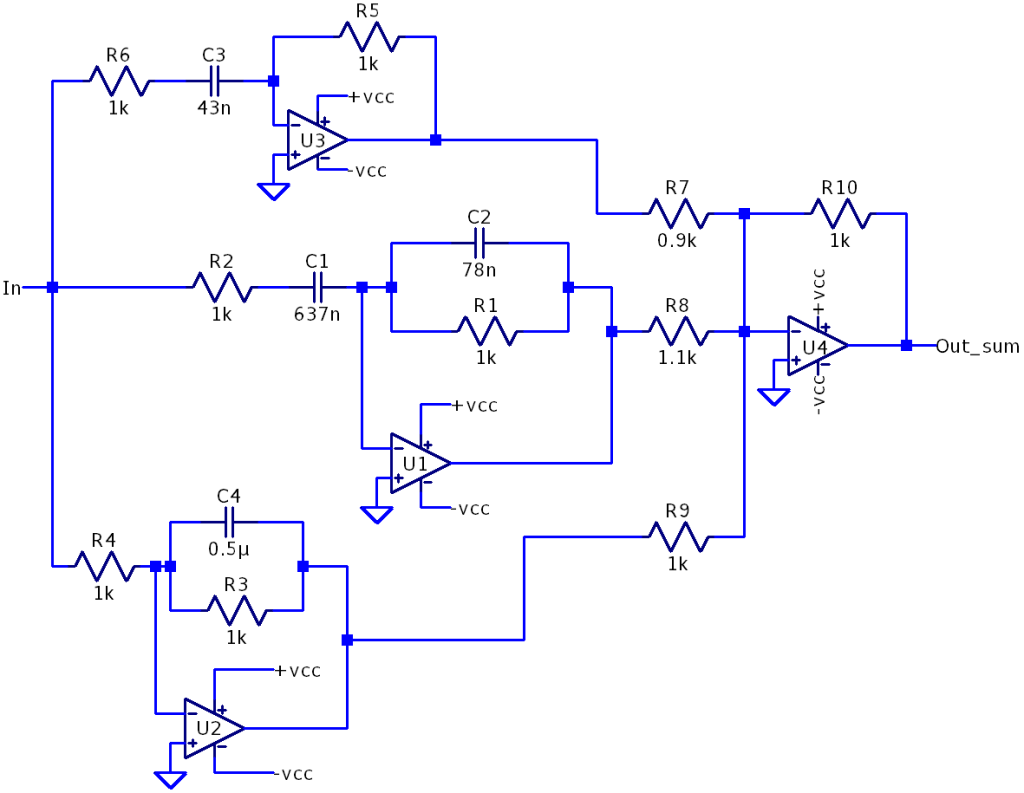
And this was the resulting spectrum:
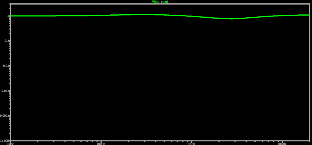
The result appeared sufficiently flat to ensure that each frequency band was evenly covered.
1.1.3.2 Equalizer Simulation
We can now test this signal to see if the behavior is close to what was expected.
Let’s start by reducing the gain of the low-pass filter, which means attenuating the low frequencies. Note that, based on the gain equations presented earlier, we can adjust this amplitude by varying the value of resistor R1. The resulting output is shown below:
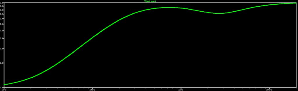
Now, let’s attenuate the high frequencies:
Finally, let’s attenuate the mid frequencies:
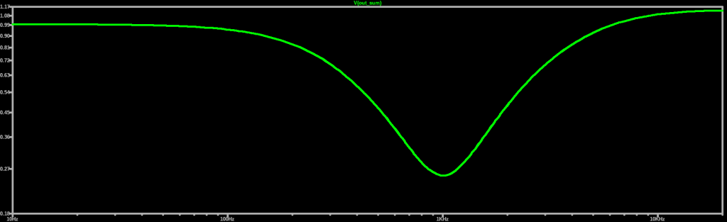
Based on these results, I felt confident that, for an equalizer using first-order filters, it was fully functional.
1.2 Operational Amplifier
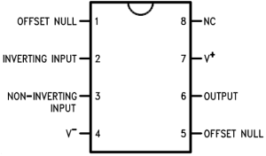
At this point, it was essential to choose the operational amplifier I would use. I had many LM741 amplifiers at home, so as a first option, I decided to use them. However, after some research, I found that this amplifier model is too noisy for audio applications, which motivated me to look for other options.
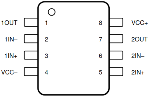
After reading some discussions in DIY guitar pedal forums, I found that the two most commonly used options were the NE5532 and the TL072. My choice was as straightforward as possible: I selected the one that my favorite electronics store had in stock, which was the TL072. To my delight, they were extremely affordable. Unlike the LM741, the TL072 contains two operational amplifiers inside, which seemed like an excellent way to save space in the final assembly.
After discussing with my Electrical Circuits professor (thank you, Leonardo R.A.X.), we concluded that the TL072 alone would not be able to provide enough power to drive speakers or headphones.
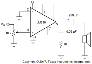
Thus, it was necessary to also add a power amplifier. Since this is a basic and low-cost project, I determined that the LM386 would be more than sufficient. This chip is a low cost power operational amplifier commonly used in basic audio applications, such as telephone and laptop speakers.
After analyzing the LM386 datasheet provided by Texas Instruments, I selected the recommended topology to achieve a gain of 20. This topology includes a 10 kΩ potentiometer, which is used to adjust the gain applied to the signal:
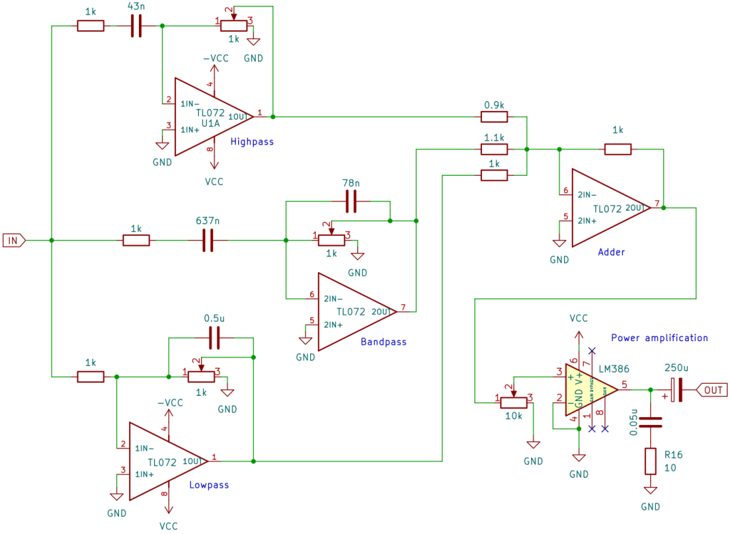
Combining everything discussed so far and adding potentiometers to adjust the amplitudes of our filters, our equalizer at this stage looks like this:
1.3 Best Practices for Equalizer Design
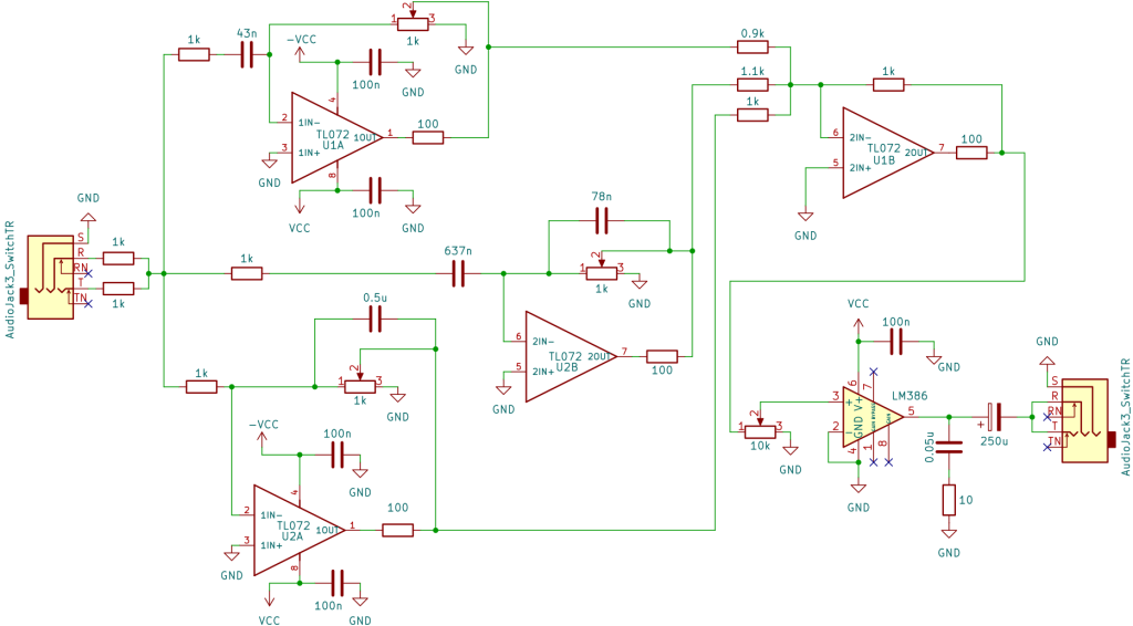
The final schematic, after the application of some improvements that are explained in this section, is shown in the following picture:
1.3.1 Noise Reduction
After reading several articles and tutorials online, I realized that one of the main concerns in audio applications is noise prevention and treatment. This is crucial because small changes can significantly improve the listening experience.
Additionally, when using the LM386 for power amplification, we are not only amplifying the signal from the filters but also any noise present in the circuit. Therefore, this must be carefully considered.
To address this, I implemented the following measures:
Feedback Resistors in the TL072: I also decided to place 100Ω resistors in each feedback line of the TL072. When an operational amplifier switches states rapidly, it is common to have current spikes in the feedback loop. Besides generating noise, this can also shorten the lifespan of the chip. These 100Ω resistors help protect the op-amp’s internal transistors from these effects.
Proper Grounding: It is essential to carefully plan how the circuit will be grounded; otherwise, it will become more susceptible to picking up external noise. Large and thin ground traces should be avoided, as they can act as antennas, making the circuit pick up radio frequency interference, for example. It is preferable to use uniform and planar grounding;
Decoupling Capacitors: These are conventional capacitors placed between the power supply and ground to reduce high-frequency oscillations from the power source. In other words, they act as low-pass filters. When placed as close as possible to the op-amps, they help maintain a stable power supply, ensuring that our operational amplifiers operate at approximately constant voltages. This reduces the noise heard in headphones.
1.3.2 Symmetrical Power Supply
Although not explicitly mentioned, using a well-structured symmetrical power supply is also crucial. This prevents the power source from behaving undesirably and keeps the output voltage as stable as possible. We will discuss this in more detail in a later section.
1.3.3 Equalizer Audio Signal Input/Output
Additionally, to facilitate audio signal output, I decided to use P2 audio jacks. To keep the project simple, I designed my equalizer to be mono, meaning the sound in the left channel is the same as in the right channel. To achieve this, I had to merge the left and right channels of the jack.
A direct connection is not recommended because the outputs of audio devices may interfere with each other, causing distortion or even damage to the circuit. To solve this issue, I placed 1 kΩ resistors in each channel before merging them. However, this step is not necessary for the output jack.
1.4 Symmetrical Power Supply
To power our operational amplifiers, I checked the TL072 and LM386 datasheets and found that they operate well at ±12 V. At the beginning of this project, I had not yet built my symmetrical power supply, and it was one of the last steps I worked on.
During the testing and assembly phase on the breadboard, I powered the circuit using the DC Agilent E3631A power supply. The need to build a symmetrical power supply arose because it was inconvenient to rely on my university’s lab for power. Therefore, I sought to understand how a symmetrical power supply works and its main stages (as I had not yet covered this topic in my coursework).
After reading several articles, it became clear that a symmetrical power supply consists of four main stages:
- Transformer: Steps down the mains voltage to 12 V AC in my case. It must have a center tap to generate two symmetrical voltages;
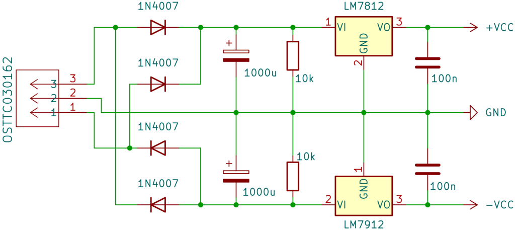
- Rectification: Converts alternating current (AC) into pulsating direct current (DC). It uses four diodes in a bridge rectifier configuration to ensure both halves of the AC cycle are used;
- Filtering: Capacitors smooth out the rectified voltage, reducing ripple and making it more stable;
- Voltage Regulators: Regulate and stabilize the output voltages. I used the LM7812 to regulate the positive voltage (+12 V) and the LM7912 to regulate the negative voltage (-12 V).
Knowing this, I followed this tutorial to assemble and design the symmetrical power supply. The figure below includes the last three stages mentioned and represents the topology we will use in our circuit. Remember the transformer is omitted in the figure.
With the power supply, we conclude the schematic design of the equalizer. Based on what has been presented, we expect to obtain a modest, low-cost, and functional circuit.
2. Equalizer Build
2.1 Breadboard Prototype
Before assembling the PCB, I considered it essential to test my circuit on a breadboard to get an idea of how the equalizer would perform. This way, I could make any necessary adjustments before finalizing the design.
2.1.1 Breadboard Build
For this phase, I had the support of my coursemate Kelvin E. Neiva, who joined me in assembling the circuit on the breadboard.
Although this is a hands-on stage, it is crucial to make all connections carefully and test the circuit as you build it. After a long afternoon of assembly, the prototype looked like this:
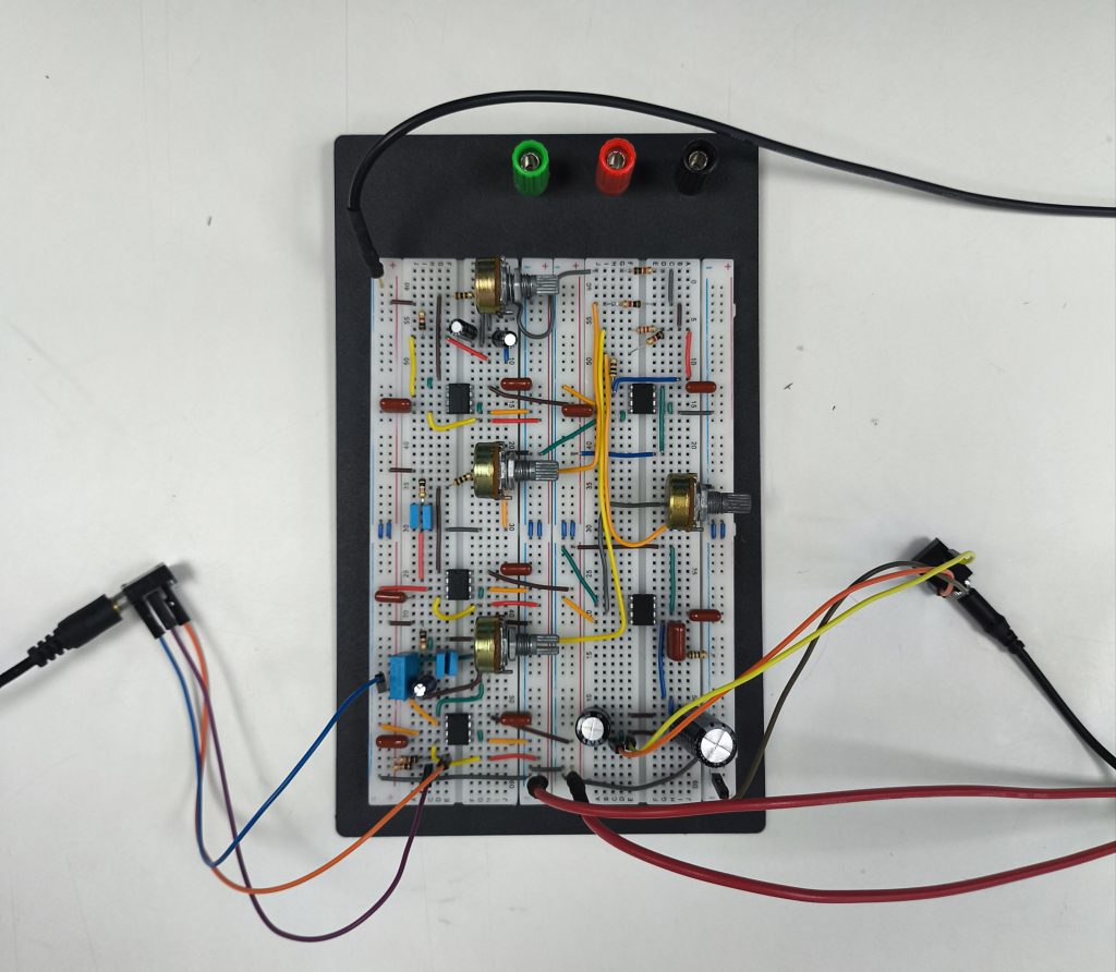
Note that while our schematic uses two TL072 and one LM386, our prototype uses more. This is because I found the circuit to be too cramped, which led me to allocate one TL072 for each filter and one for the summing amplifier, totaling four TL072 and one LM386. This change was made solely to simplify the breadboard assembly.
Additionally, to achieve the calculated capacitance and resistance values, I had to make some approximations and combine capacitors available at my favorite electronics store. Far from ideal, I had to use electrolytic capacitors in some parts of the circuit due to availability issues. These capacitors, besides being polarized, have high tolerances, which can slightly alter the transfer function of the filters. Therefore, I encourage you to prioritize film capacitors, which are better suited for audio applications.
2.1.2 Breadboard Results
It is important to note that the sound quality of the equalizer on the breadboard tends to be significantly lower and noisier compared to the PCB version. This is because the presence of jumpers, long wires, oxidized surfaces, and weak grounds significantly increases circuit noise.
Due to the limited grounding on the breadboard, my prototype picked up radio frequency waves, allowing me to hear a local radio station. This highlights the importance of proper grounding!
Despite these considerations, the equalizer was functioning, and I was ready to move on to PCB assembly.
2.2 PCB Prototype
2.2.1 PCB Design
This was my first time developing a PCB, so I had to learn everything from scratch. After researching the best PCB design tools, I decided to use KiCad. I chose it because the community was very active, and the software was FOSS (free and open-source software).
With this in mind, I used the time I spent commuting to university by subway to read KiCad Like a Pro – 3rd Edition by Peter Dalmaris. This provided me with a solid foundation to start designing.
It took dozens of attempts to reach a version that truly satisfied me. Since my goal was to make a homemade PCB, I had to make the following decisions:
- Single Copper Layer: This would simplify the PCB manufacturing process. I only needed to worry about one side of the PCB, avoiding vias and potential workarounds;
- Trace Width: I decided to use 1 mm traces. This might seem wide, but I preferred to err on the side of caution, especially since this was my first time making a homemade PCB;
- Grounding: As previously mentioned, grounding is crucial in audio applications to avoid noise and interference. Therefore, I adopted a ground plane, which involves using all remaining PCB space for ground connections. This method reduces ground impedance, minimizing noise and improving signal integrity, especially in high-frequency circuits.
After implementing these measures, my PCB design looked like this:
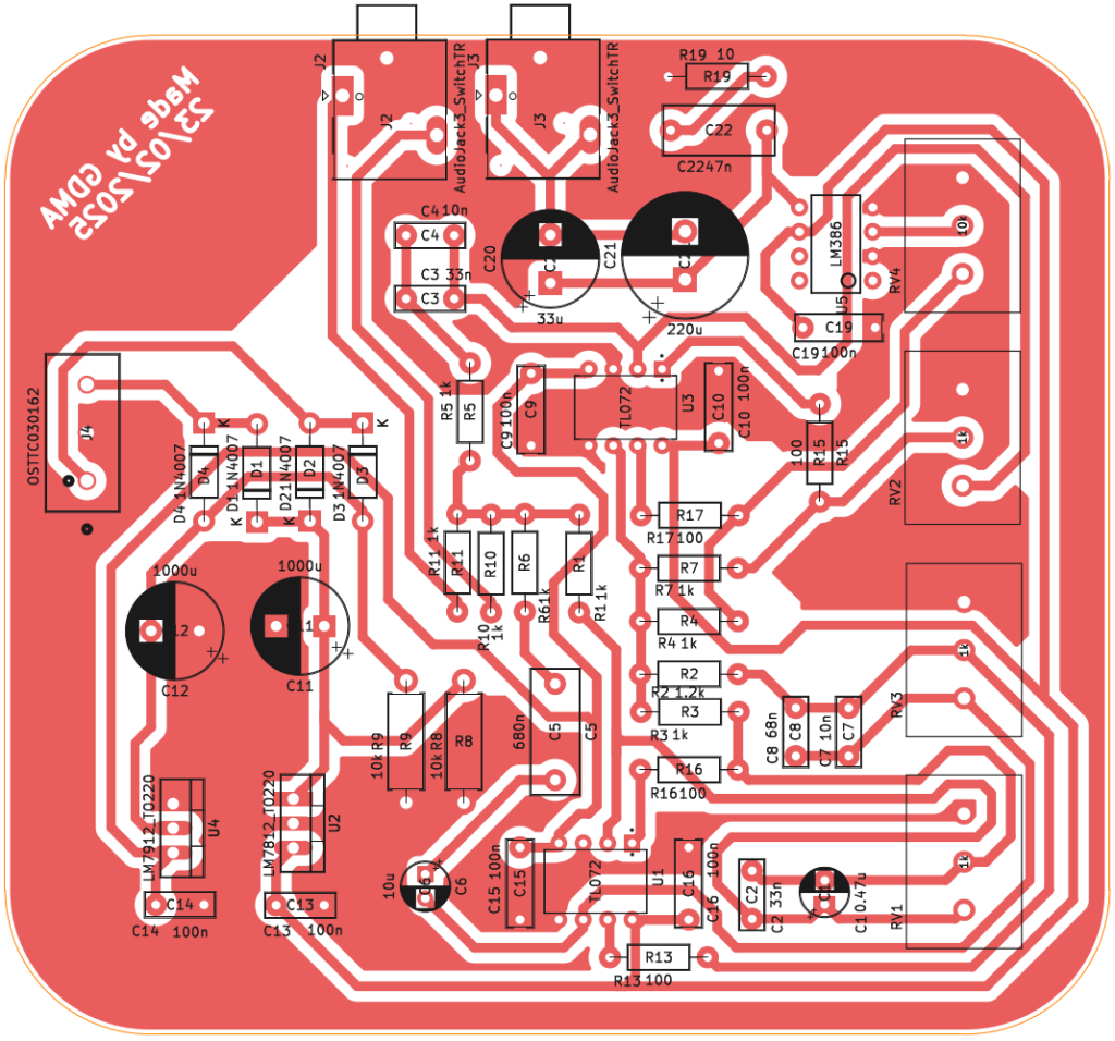
Once again, due to availability issues, I had to use electrolytic capacitors in some parts of the circuit and make some approximations, which is far from ideal. Always prioritize film capacitors for audio applications.
2.2.2 PCB Assembly
To manufacture and assemble the PCB, I used the toner transfer method followed by copper etching with ferric chloride.
If you’re interested in understanding how this process works, we have a tutorial on Electroagenda (link). Therefore, I will be brief.
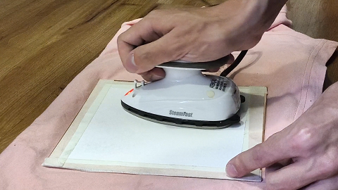
The first step was to print my circuit on photographic paper and transfer the toner ink to the copper-clad phenolic board using an iron:
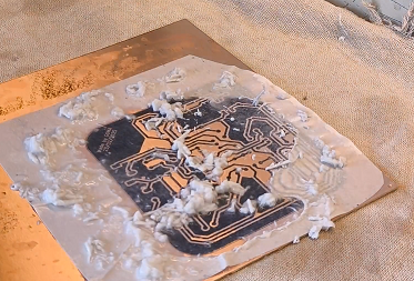
After heating the surface for about 10 minutes, I let it cool down and removed the paper by rubbing it with warm water:
After removing all the paper, I cut the board and sanded the edges to improve the finish:
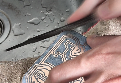
With that done, it was time to etch the copper surface using ferric chloride. I recommend wearing gloves to prevent accidents.
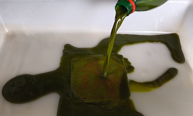
After waiting about 20 minutes, the copper was fully etched. Once you store your ferric chloride solution, I recommend neutralizing any remaining acid in the container with a baking soda solution. This prevents unwanted reactions when washing the container.
With the board etched, the next step was drilling the holes. I selected the smallest drill bit I had and carefully drilled each hole:
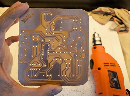
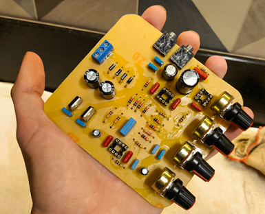
With all the holes drilled, it was time to solder the components. To ensure good connections, I used plenty of solder flux. After that, I cleaned the board with isopropyl alcohol and tested all connections with a multimeter. The PCB was finally ready:
2.3 Equalizer Assembly
To power the circuit, I still needed to install the 12 V transformer. To keep everything secure and practical, I decided to mount both the transformer and the PCB on a wooden base:
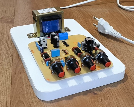
Finally, the equalizer was complete, only the final test remained:
3. DIY Equalizer Results and Conclusions
Compared to the prototype, the noise was significantly reduced, and the equalizer stopped picking up radio frequency waves, indicating that my grounding was effective.
I tested it with an 8 Ω speaker and a 16 Ω pair of headphones. Personally, I preferred the sound from the 8 Ω speaker — it seemed clearer and slightly more vibrant to me. Additionally, on both devices, I could clearly notice the difference between bass, midrange, and treble.
Since the LM386 is a low-cost chip designed for simple applications, increasing its gain too much also significantly increased the audible noise. To achieve good audio quality, it was necessary to balance the music volume with the equalizer’s gain.
With this article, I hope to have shared both my insights and my mistakes so that others can benefit from the experience and perhaps even improve the project.
Feel free to suggest corrections and improvements to the assembly. All knowledge exchange is welcome!
Annex 1. List of Materials
| Description | Part Number Value | Quantity |
| Electrolytic Capacitor | 0.47u | 1 |
| Electrolytic Capacitor | 10u | 1 |
| Electrolytic Capacitor | 1000u | 2 |
| Electrolytic Capacitor | 220u | 1 |
| Electrolytic Capacitor | 33u | 1 |
| Polyester Capacitor | 33n | 2 |
| Polyester Capacitor | 10n | 2 |
| Polyester Capacitor | 680n | 1 |
| Polyester Capacitor | 68n | 1 |
| Polyester Capacitor | 100n | 7 |
| Polyester Capacitor | 47n | 1 |
| Diode | 1N4007 | 4 |
| Jack Socket | 3.5mm | 2 |
| Terminal Block | 3P | 1 |
| Resistor | 1K | 11 |
| Resistor | 1.2K | 1 |
| Resistor | 10k | 3 |
| Resistor | 100 | 4 |
| Resistor | 10 | 1 |
| Operational Amplifier | TL072 | 2 |
| Operational Amplifier | LM386 | 1 |
| Regulator | 7812 | 1 |
| Regulator | 7912 | 1 |
Subscription
If you liked this contribution, do not hesitate to subscribe to our newsletter: