DIY Poor’s Man Music Synth Developed and Written by Aman Deep.
This project presents a digital monophonic square wave synthesizer and sequencer. In other words, a digital music synthesizer, or music synth. It is based on 555 oscillator and 4017 decade counter. This device offers a distinctive sound reminiscent of vintage video games and early digital audio devices.
The table of contents is as follows:
1. Introduction to Music Synths
As the name suggests, a music synthesizer is an electronic device that synthesizes and produces music. Synthesizers works by producing, altering and adjusting electronic waveforms. They operate on raw waveforms like square, triangular, sinusoidal, and saw tooth produced by oscillator circuits. The waveforms are altered using methods like additive and subtractive synthesis.
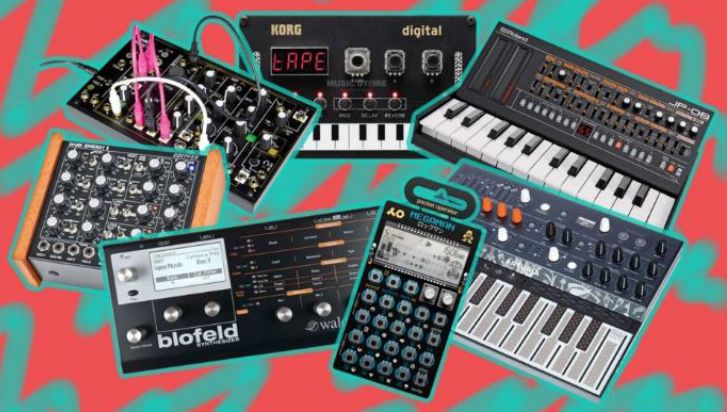
Synthesizers are the most crucial components of modern-day music and culture, as they have shaped and propelled various well-known genres like Electronic Music, Synthpop, Hip Hop, and Trap music to the multitude.
1.1 Music Synths Components
The fundamental elements that can be found in a music synthesizer for producing and altering the waveforms are:
- Low Frequency Oscillators: to generate the waveforms.
- Filters: circuits that separate different band of frequencies.
- Sequencers: circuits that introduce a sequence in which the notes will be played.
- Envelope Controllers: circuits that modulate the amplitude.
1.2 Music Synths Classification
According to the processing strategy, music synths can be hardware based (analog or digital) or software based, each having unique and characteristic capabilities.
On the other hand, music synths can be monophonic, producing a single note at a time, or polyphonic, producing multiple notes simultaneously.
Finally, music synths can be either a stand-alone device, that produces notes, or a multi-device structure equipped with controllers and synchronizers like keyboards, sequencers, and software.
2. The Monophonic Music Synth
This music synth is built around three functionalities or specifications:
- Inbuilt sequencer.
- Should have a way to select which notes to play.
- Must provide a way to visualize the sequence of the notes, thus enabling the user to mix notes live.
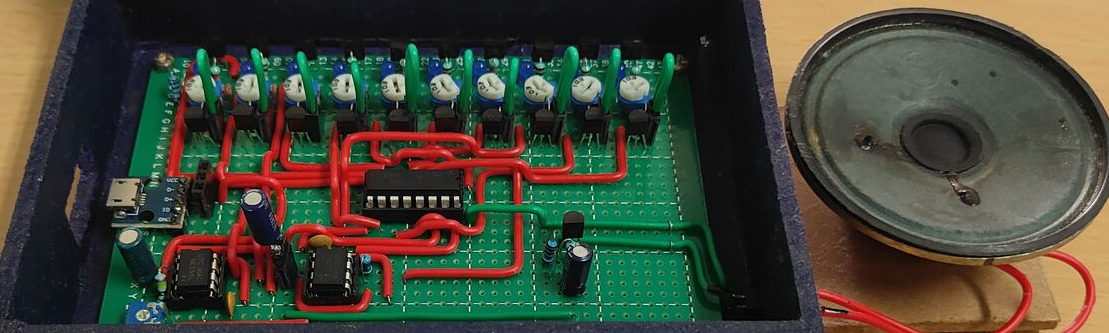
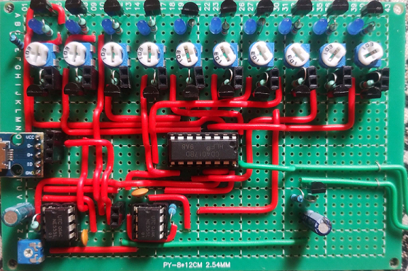
The designed and built device is shown in the following picture:
2.1 Key Features
Overall, this is a digital monophonic square wave synthesizer with the following key features.
2.1.1 Resolution: 1 Bit
The synth offers output resolution of 1-Bit. Here the output is colloquially referred to as a 1-Bit output in reference to the inherent operation of the synthesizer, which can produce a single note at a time (monophonic synth), with the waveform being a square wave of constant amplitude.
This property of the synth gives it a distinctive sound of vintage video games, even preceding 8-bit music.
2.1.2 Onboard Sequencer
The synth has an onboard sequencer which allows note selection speed, which is perceived by us in the form of tempo. It enables the user to create unique music and have precise control over its pace.
2.1.3 Onboard Note Selector
The synth has a series of toggle switches that are used to select which notes will be played when the output from the sequencer reaches the selector stage. This allows the user to compose and arrange the notes in patterns, achieving sounds that are perceived as music.
2.2 Music Synth Schematic
The following picture shows the schematic of the device:
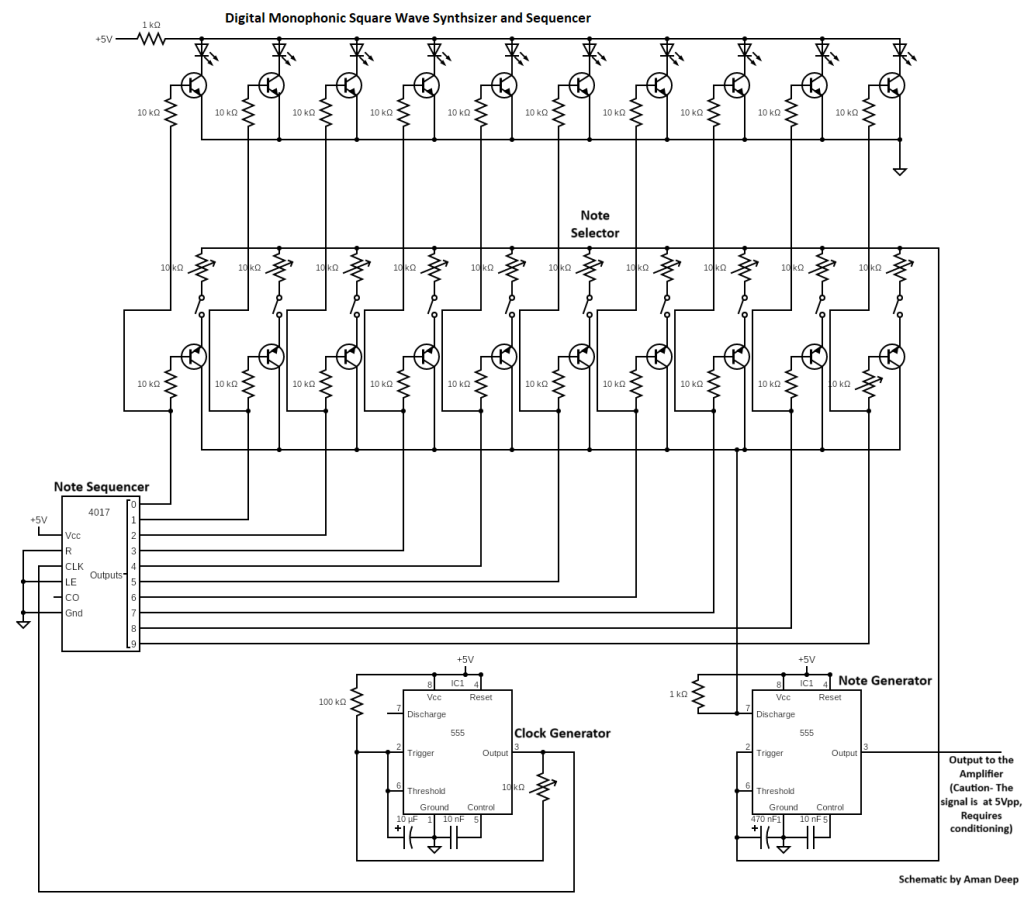
Next, every stage is explained in detail.
2.2.1 Clock Generator
The Clock Generator stage provides a clock to the decade counter, which serves as the sequencer. The clock stage serves as music pace controller in the synth.
It consists of a 555 timer that generates a square wave with a 50% duty cycle. As you vary the potentiometer in the clock generator circuit, the output frequency of the circuit changes, causing a change in how fast the counter of the sequencer goes through its states, thus changing the pace of the sequence of the notes being played.
For a full explanation of the clock generator, please have a look to the annex below, focused on oscillators and the 555 integrated circuit.
2.2.2 Note Sequencer
The output from the clock generator is fed into the note sequencer stage, which executes the pace of the generated music. The note sequencer stage, as the name indicates, sequences the notes that will be later reflected at the output of the synth. It just simply “enables” in order each one of the notes configured in the note selector.
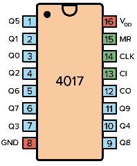
The circuit consists of a decade counter. Basically, it is a circuit that counts 10 clock pulses and outputs in a format specific to the IC employed. Here, we employed the IC 4017, which outputs the count of 10 pins, each assigned a decimal value from 0 to 9, representing 10 counts. This property of the decade counter to provide 10 distinct outputs serves as the fundamental algorithm for the ability of the synth to have 10 different notes. When the counter cycles through its 10 outputs by responding to the clock, it works as a sequencer in the synth.
2.2.3 Note Generator
The note generator stage is responsible for the production of individual musical notes that, when played in an order, create music. It is handled by the second oscillator circuit. Again, more details of the 555 timer can be found in the annex below.
The note generator works with the note selector, which has 10 potentiometers connected in parallel. As explained in the next section, each potentiometer can be set to a value, depending upon the frequency the user wants to produce, according to the formula discussed in the oscillators annex below. In other words, each potentiometer selects a frequency for that note. By using the potentiometers, the output frequencies can be varied and modified in real time.
2.2.4 Note Selector
The note selector is a parallel transistor-potentiometer-switch array (that is part of the note generator circuit) and is responsible for the selection of different notes.
Firstly, the note selector stage takes input from the note sequencer stage, which operates the transistor array by switching them ON and OFF. Remember that only one transistor of the array can be active at any time.
Then, the note selector stage works by switching the transistors one by one in a sequence, thus connecting one potentiometer, having some set resistance at a time to the input pins of the note generator. This operation results in a unique note that can be played at the output of the note generator at that moment.
Note that there is also a manual note activation, performed by the switches connected in series with the potentiometers. When OFF, there is no connection of that particular potentiometer to the note generator, resulting in no note being played at the output. This gives the user the functionality of which notes they want to play in the sequence.
2.2.5 Sequence Display
The sequence display is an array of LEDs controlled by transistors that are switched by the output pins of the counter. They serve the purpose of providing visual aid to the user for the pace or speed of the sequence. The LEDs corresponding to each pin turn ON when the pin is high during the sequence.
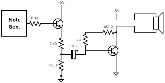
2.2.6 Signal Conditioning and Amplifier
The synth also includes a direct unconditioned output from the tone generator which has a peak-to-peak voltage of 5V. It can be accessed through the middle one out of the three breakout female headers besides the USB port.
A simple way to condition this signal is by including a voltage divider which gives a voltage output of 2.2Vpp, which is suitable for most amplifiers and loudspeaker systems. A transistor is used to prevent the loading of the output of the note generator, and the output is fed into the base of the transistor amplifier through its base resistor. The on-board amplifier on the music synth is a simple common collector configuration.
Overall, the output schematic is as follows:
3. Video and Sound
The sound of the device can be listened to in the following video:
4. Conclusions
Throughout the Digital Music Synthesizer Project, we have attempted to achieve the fusion of Electronics, Creativity, and Art. It is clear that the device is inspired by early devices that made significant achievements in the realm of electronic music.
The Music Synth boasts three main features: an inbuilt sequencer, a note selection mechanism, and a real-time sequence visualization feature. These features are made possible through the integration of five distinct stages. The Clock Generator sets the tempo of the music, allowing users to control the pace of the music. Coupled with the Note Generator and The Note Selector and Sequencer, which produce individual notes based on user input, the Music Synth enables users to create and compose their own sound. The Note Sequencer can compose these notes in real time, ensuring uninterrupted playback. In addition, the Note Selector gives users the ability to choose which notes to include in the sequence, adding a personal creative touch to the music-making process.
This Music Synth is a versatile and user-friendly tool for music enthusiasts of all levels. It offers a direct output that can be integrated with other equipment to expand its usage, ensuring its versatility at any level of music production. With its intuitive design and many features, this project provides a great opportunity for exposure to Electronic Music.
Annex 1. List of Materials
| Description | Part Number Value | Quantity |
| Resistor | 100K | 1 |
| Resistor | 10K | 20 |
| Resistor | 1K | 2 |
| Potentiometer | 10K | 11 |
| Electrolytic Capacitor | 10uF | 1 |
| Electrolytic Capacitor | 470nF | 1 |
| Ceramic Capacitor | 10nF | 2 |
| IC | NE555 | 2 |
| IC | CD4017 | 1 |
| Transistor | BC547 | 20 |
| LED | 3mm Blue | 10 |
| Switch | SPST Toggle | 10 |
| Speaker | 8Ω | 1 |
| Proto PCB | 2.54 mm 8x12cm | 1 |
Annex 2. Oscillators
Oscillators in electronics are devices that produce periodic and oscillating or alternating signals like AC, square, sinusoidal (sine), triangular, or saw tooth waves. These generated waves are then used to synchronize, drive or as a raw input in electronic circuits. The presented synth consists of two oscillators that are deployed using 555 timer ICs.
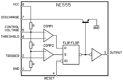
A2.1 Timer Integrated Circuit 555
The 555 timer IC is an integrated circuit used in various timer, delay, pulse generation, and oscillator applications. The 555 timer gets its name from the presence of three 5KΩ resistors connected in series to create a voltage divider that provides reference voltage for its internal comparators.
A2.2 Astable Multivibrator
An astable multivibrator is a type of electronic oscillator circuit that continuously produces a square wave output. As the name suggests, this type of oscillator has no stable states i.e. it keeps alternating between high and low state on a regular interval. The circuit switches back and forth between the two states, generating a continuous oscillating output.
The following picture shows an astable multivibrator configuration of the 555 Timer:
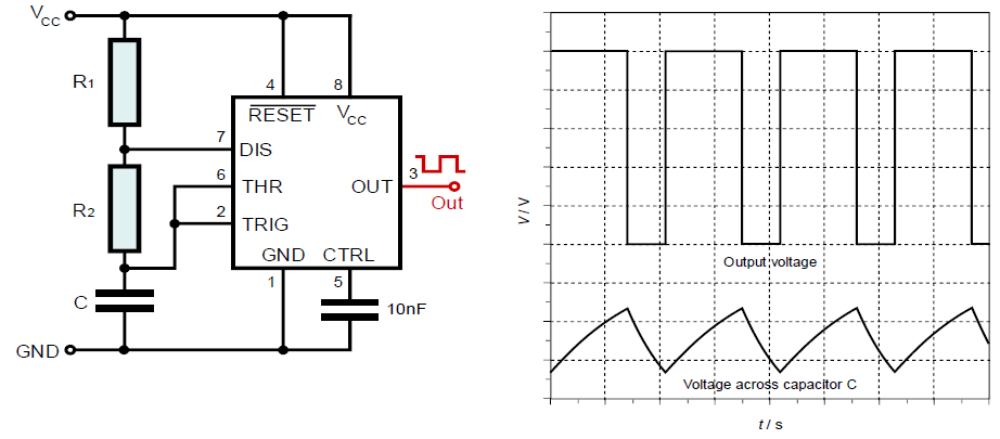
The voltage divider sets the reference voltage for the comparator 1 at 2/3 𝑉𝑐𝑐 and for Comparator 2 at 1/3 𝑉𝑐𝑐.
When 𝑉𝑐𝑐 is applied, the Capacitor C charges through (R1 + R2) and it charges until its voltage reaches 2/3 𝑉𝑐𝑐. Then the comparator 1 causes the internal flip-flop to flip its state, which turns ON the transistor at discharge pin 7, and the capacitor C starts to discharge through Resistor R2. The Capacitor 𝐶 discharges until its voltage reaches 1/3 𝑉𝑐𝑐 and the comparator 2 causes the internal flip-flop to flip its state. That turns OFF the transistor at discharge pin 7, and the capacitor starts to charge again.
The cycle repeats, causing a square wave output due to the periodic change in the state of the internal flip-flop.
A2.2.1 Note Generator
The note generator consists of an astable configuration of the 555 timer, as explained above. The output frequency is given by the formula:
\begin{equation} f = \cfrac{1.44}{(R_1+2R_2)C} \end{equation}
By using this formula and varying the variables such as R2 and C in our circuit, the output frequency can be varied. Thus, producing notes of different frequencies.
A2.2.2 Clock Generator
A clock in electronics is an oscillating signal that is used to step a digital circuit through its various states in a sequential manner.
This configuration uses a resistor between the trigger and output pins of the 555 timer, and no connection to the discharge pin. Therefore, the capacitor charges and discharges through the same resistor, thus taking the same amount of time, which results in 50% duty cycle square wave at the Output.
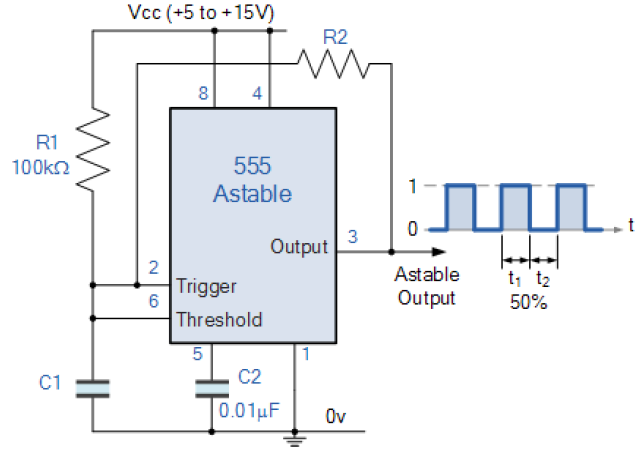
The output frequency in this configuration is given by the formula:
\begin{equation} f = \cfrac{1.44}{2R_2C} \end{equation}
It can be varied to change the tempo of the sequence by using the potentiometer R2, given that R1 is significantly greater than R2.
Subscription
If you liked this contribution, do not hesitate to subscribe to our newsletter: