
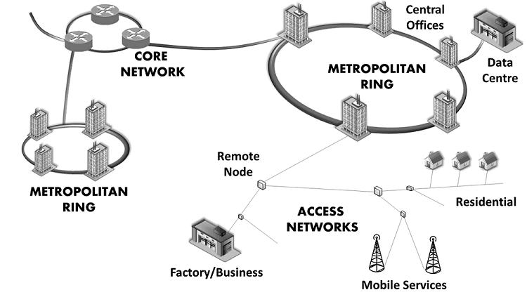
This section provides a basic classification of optical networks. The overall network is a complicated system that ensures robust optical communications between exchange information nodes. This high-level system can be divided into typical subnetworks that meet specific geographical and functional requirements: the core network, Metropolitan Area Networks (MAN), access networks and Local Area Networks (LAN).
networks.
The previous picture illustrates the different suibnetworks. Each subnetwork is briefly described below according to the following table of contents:
1. Core Network
The core network is the backbone of the global optical communications system. It interconnects areas separated by hundreds or thousands of kilometres and, consequently, its longer subsystems are also referred to as long-haul links. It consists of both terrestrial and submarine links that transport aggregated data from MANs located in different cities, countries or continents. This is made possible by combining a number of technologies: distributed optical amplification, advanced modulation formats, Dispersion Compensating Fibres (DCF), Forward Error Correction (FEC) codes and coherent detection.
Legacy core networks employ a Time Division Multiplexing (TDM) scheme, known as Synchronous Digital Hierarchy (SDH) or Synchronous Optical Networking (SONET), to carry voice and data services such as IP or Asynchronous Transfer Mode (ATM). In WDM core networks, every wavelength carries an SDH/SONET service at typical rates of 2.5 or 10 Gbit/s. Modern core networks are transitioning towards a new protocol, Optical Transport Networks (OTN) defined in the International Telecommunication Union (ITU) standard G.709. OTN accepts a wide variety of client services like IP, Ethernet, ATM or legacy SDH/SONET, and provides transport and management over WDM networks exploiting its multi wavelength capabilities. Data rates beyond 100 Gbit/s per wavelength are supported.
2. Metropolitan Area Networks
MANs provide the connection between Central Offices (CO) in a metropolitan area. COs are the locations where telecommunication operators and Internet Service Providers (ISP) connect their overall network infrastructure to the access networks that serve their subscribers and clients. COs are typically separated by less than 100 kms, which reduces the cost of the deployed technology in comparison with long haul links.
Typical MANs present a ring topology that is served with SDH/SONET in the physical layer, similarly to core networks. Due to the recent growth of video services and data centres, it is estimated that metro traffic will increase two times faster than core traffic. Until recently, a single wavelength configuration was sufficient. The traffic growth was absorbed increasing the data rate up to the SDH/SONET 10 Gbit/s configuration, once it became affordable for MANs. The transition towards WDM MANs is now in progress, using existing commercially available equipment that can multiplex 10 Gbit/s services and beyond in each wavelength.
3. Access Networks
Access networks connect the final customers with a CO in the MAN, usually implementing links of less than 20 kms. Apart from voice and data services for residences and business, access networks also include Cable Television (CATV) systems and Radio Access Networks (RAN). The bitrates involved in access networks are not very high, but they present important technical challenges due to the non-uniform distribution of users.
3.1 Legacy Networks
Currently, the most common access networks employed for voice and data are based on the legacy Plain Old Telephone Service (POTS). They use a pair of twisted copper wires and were originally designed for transmitting voice. However, a technique called Asymmetric Digital Subscriber Line (ADSL), based on the transmission of multiple subchannels, maximise the potential of these wires reaching potentially 24 Mbit/s in the downlink and 3.3 Mbit/s in the uplink.
In contrast, CATV systems required coaxial cables even in the initial implementations, as they multiplexed a number of 8 MHz analogue video channels in the same cable. The main drawback of this method is that it requires amplifiers or regenerators every few hundred meters. For that reason, Hybrid Fibre-Coaxial (HFC) systems were adopted. They transmit the broadband signal from the CO over fibre and a node close to the end users performs the opto-electrical conversion. Finally, the signal is distributed to the customers with coaxial cable in a point to multipoint configuration.
These HFC networks have evolved to also offer voice and data services. The standard that rules this technology is the Data Over Cable Service Interface Specification (DOCSIS). The most recent developments employ OFDM to achieve 10 Gbit/s in the downlink and 1 Gbit/s in the uplink. These bitrates are shared and, normally, the highest end user rates are limited to < 1 Gbit/s in the downlink.
3.2 Passive Optical Networks
3.2.1 Relevance
The deployment of optical access networks purely based on optical fibre, normally defined as Fibre To The Home (FTTH) solutions in residences, is not widespread. Substituting the installed electrical links based on copper by point to point optical links would be very expensive for network operators. Instead, most efforts are focused on a cost efficient tree-like point to multipoint solution defined as Passive Optical Network (PON).
3.2.2 Implementation
An illustrative diagram of a PON is shown in the figure below, in a TDM implementation. The Optical Line Terminal (OLT) is the unit or the equipment located at a CO or a remote node that controls and manages the connection with the end users, referred to as Optical Network Units (ONU). Only the OLT and the ONUs require active equipment which reduces the cost.
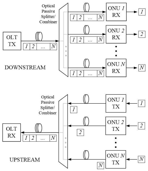
For the downlink, the data for all the users is generated and introduced in a single fibre by the OLT. At some point close to the customers, a passive splitter produces multiple replicas of the multiplexed signal and each one is transmitted to a different ONU. When the ONU receives the signal, it decodes the information that was allocated for it. For the uplink, each ONU transmits information and the passive device combines and multiplexes all the incoming signals in a single one that is then received in the OLT.
3.2.3 Data Rates
First generation gigabit PONs, often called G-PONs, multiplex the data in time (TDM), typically reaching shared rates of 2.5 and 1.25 Gbit/s in the downstream and the upstream respectively, which translate into 80/40 Mbit/s connections for the end users. The next generation, called 10 Gigabit Passive Optical Network (XG-PON), achieves shared rates of 10/2.5 Gbit/s.
Recently, and after the proliferation of vendor-specific PONs based on WDM access, a new standard that employs TDM, WDM and sophisticated optical components was defined. It is called Next Generation Passive Optical Networks 2 (NG-PON2) and can provide connections of up to 10 Gbit/s to final subscribers. The general topologies for data (de)/multiplexing in typical applications are explained in detail in the section 4.2 of this link.
3.3 Radio over Fibre (RoF)
Optical fibres are also employed in access networks to link COs with antennas in radio applications. In general, the term Radio over Fibre (RoF) applies to the cases in which the optical link facilitates the centralisation of several wireless services in one location (the CO). Theoretically, the high bandwidth of the optical fibre allows the simultaneous transmission of all the conceivable radio bands, even Terahertz applications, in the same fibre.
3.3.1 Analogue RoF
Ideally, an analogue radio signal would be transmitted over fibre from the CO and the base station would be a simple system consisting of a receiver plus an antenna. Commercial applications based on such analogue RoF concepts have been deployed for cellular communications. Currently, most research efforts are focused on such a configuration using the free 60 GHz band for future mobile generations, 6G or Internet of Things (IoT).
3.3.2 Digital RoF
Moreover, an alternative technique called digital RoF is also being implemented and deployed. A functional example of a digital RoF system is the Common Public Radio Interface (CPRI). It supports most of the current mobile networks standards and employs the following terminology: Radio Equipment Control (REC) in the CO and Radio Equipment (RE) in the antenna. For the downlink, the REC generates the samples of the modulating signal and transmits a bitstream that contains the values of those samples over fibre. The RE uses the samples to perform the digital to analogue conversion, and then it modulates the reconstructed waveform onto the Radio Frequency (RF) carrier that is finally emitted. For the uplink, the RE demodulates the received RF signal. Then it samples the obtained waveform and transmits a bitstream with the values of the samples over fibre. At the other end, the REC receives and processes the samples.
4. Data Centres
4.1 Local Area Network (LAN)
The networks that handle the traffic of data in customer and business premises are called Local Area Networks (LAN) and meet the “Ethernet” standard from the Institute of Electrical and Electronics Engineers (IEEE) 802.3. LANs are composed of multiple users (typically computers) that are interconnected through hubs, switches, point to point links and/or a shared medium. The standard has evolved constantly during more than 30 years and several optical links with different combinations of bit rates, fibres and distances are supported. In general, the technology for these optical systems has to be cheap and appropriate for large scale markets.
4.2 High Performance Computing Systems
Data centres and high performance computing systems can be seen as particular LANs optimised for a continuous exchange of data provided simultaneously by multiple devices (typically servers). The generalisation of Internet applications accessed by thousands or millions of users has translated into the proliferation of high-capacity high performance data centres.
4.2.1 Architecture
The common data centre structure consists of racks of servers that are connected with top-of-the-rack switches by links shorter than a few meters. Switches situated at different layers route the traffic towards metro or core networks.
Several optical interfaces and standards defined by different institutions are typically employed for the connections between switches: Ethernet, Infiniband and FibreChannel.
4.2.2 Multisource Agreement Transceivers
In the optical communications industry, multisource agreements define mechanical slots plus the mechanics of their associated pluggable electro-optical transceivers to allow interoperability between manufacturers. For this particular application, the transceivers are usually designed to be compatible with the three previous standards.
Due to the constant growth of traffic in data centres, there is a continuous definition of smaller transceivers in order to increase the spatial density of data interfaces in switches. Due to its density, the transceiver that is becoming predominant is the Quad Small Form-factor Pluggable (QSFP). Currently, this transceiver integrates four lasers to implement four parallel optical channels at 25 Gbit/s, reaching an overall rate of 100 Gbit/s and supporting 100 Gigabit Ethernet (100GbE), IEEE 802.3bm.
Bibliography
[1] Fiber-Optic Communication Systems, Govind P. Agrawal
Subscription
If you liked this contribution, feel free to subscribe to our newsletter: